TYLC4 Reset & Teardown (FCC ID 2ANDL-TYLC4)
Factory reset and internal photos for Tuya Global TYLC4. Tuya / Smart Life smart plug.
January 15, 2026
•
9 read
Before you buy the Tuya Global TYLC4, check what's inside.
The TYLC4 is a low-power embedded Wi-Fi module based on the ESP8266 chipset, designed for integration into smart home devices. It operates on 3.0V-3.6V and is suitable for applications requiring Wi-Fi connectivity like smart plugs and lighting.
⚠️ NOTE: Ensure correct battery polarity and voltage (3.0V-3.6V) when powering the module.
Quick Specs
- Manufacturer: Tuya Global
- Model: TYLC4
- Protocol: WiFi
- Chipset: ESP8266
- Ecosystem: Tuya / Smart Life
- App: Smart Life
🔧 Geek Corner (Flashing Info)
- Chipset: ESP8266
- Flashable: ✅ Yes
- Info: The module uses an ESP8266 chipset and the documentation mentions Tasmota/ESPHome compatibility, indicating it can be flashed.
User Manual
Scanned pages from the official user manual:
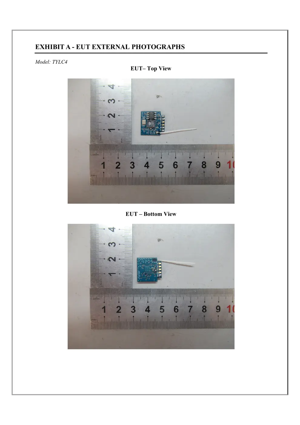
External Photos
Photos of the device exterior:
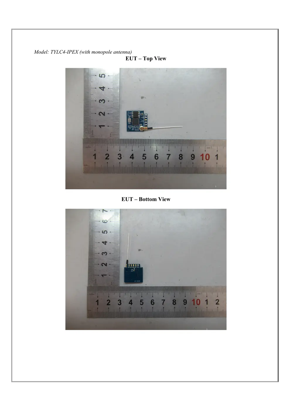
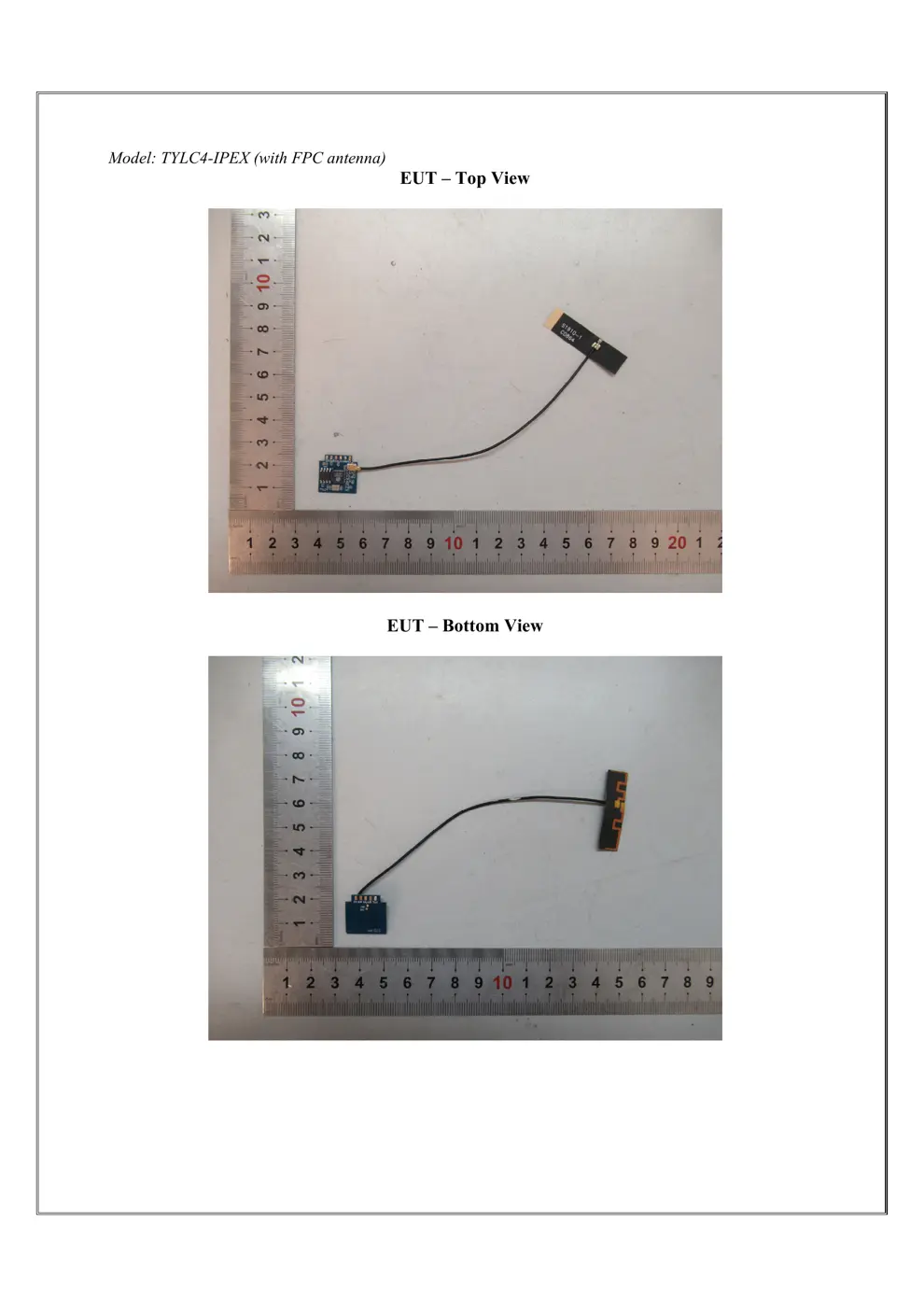
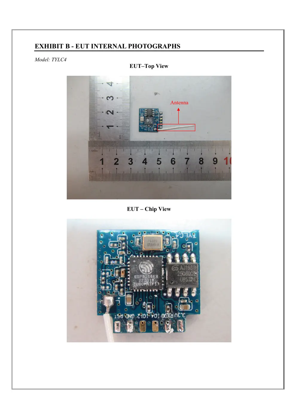
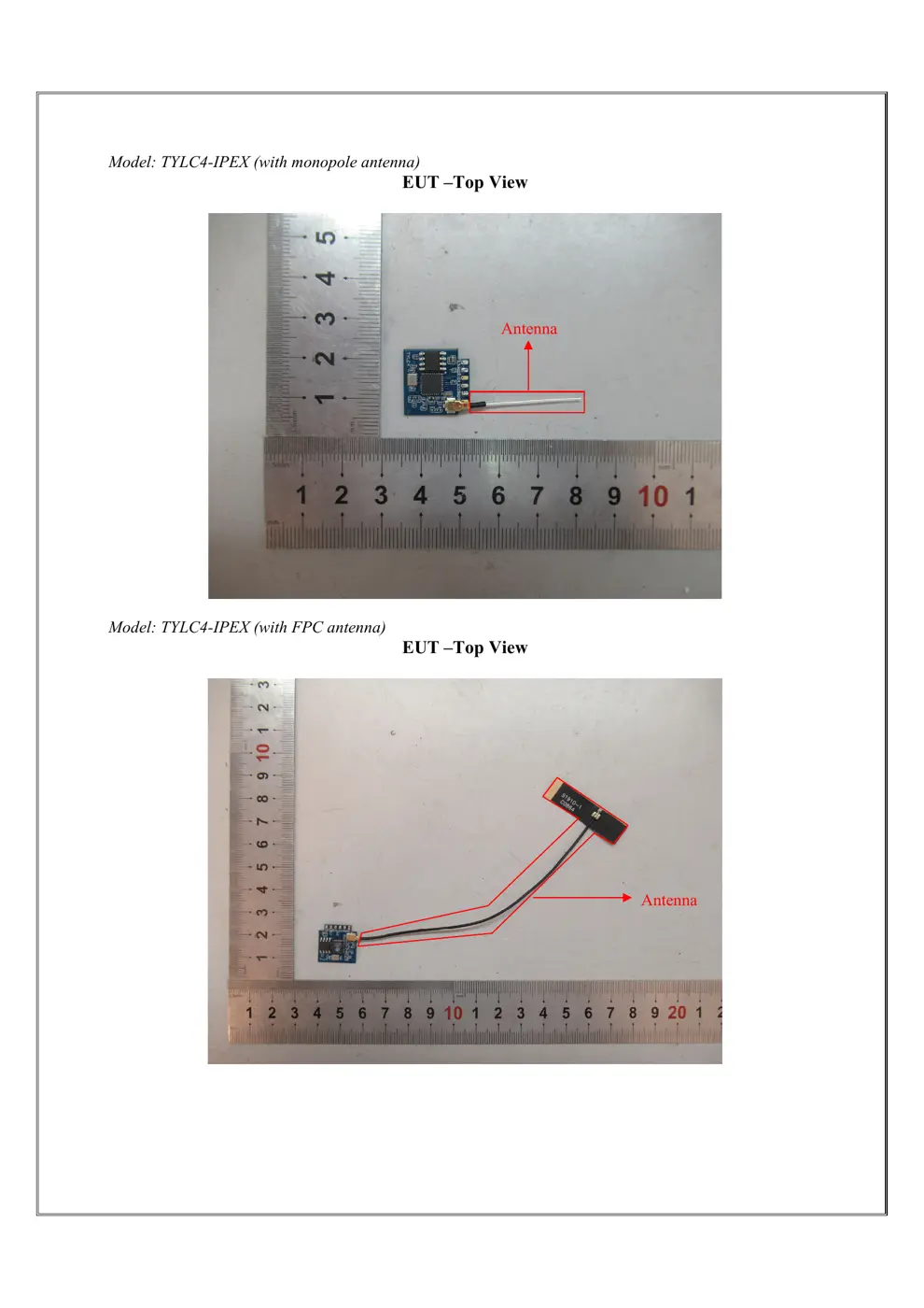
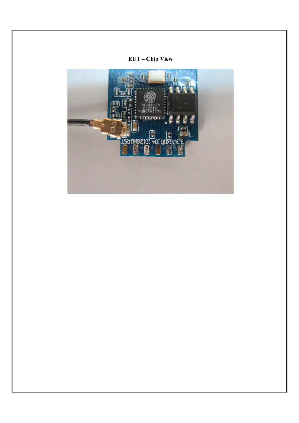
Internal Photos
Teardown photos showing the PCB and components:
Verdict
The TYLC4 is a WiFi device from the Tuya / Smart Life ecosystem.
📄 Click to view full text manual (SEO)
TYLC4v1.0.0 User manual
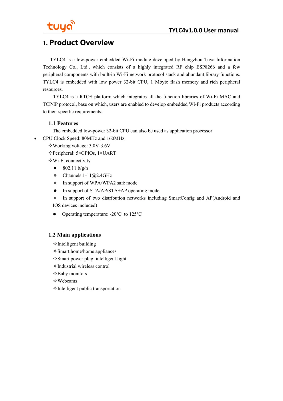
1. Product Overview
TYLC4 is a low-power embedded Wi-Fi module developed by Hangzhou Tuya Information
Technology Co., Ltd., which consists of a highly integrated RF chip ESP8266 and a few
peripheral components with built-in Wi-Fi network protocol stack and abundant library functions.
TYLC4 is embedded with low power 32-bit CPU, 1 Mbyte flash memory and rich peripheral
resources.
TYLC4 is a RTOS platform which integrates all the function libraries of Wi-Fi MAC and
TCP/IP protocol, base on
which, users are enabled to develop embedded Wi-Fi products according
to their specific requirements.
1.1 Features
The embedded low-power 32-bit CPU can also be used as application processor
CPU Clock Speed: 80MHz and 160MHz
Working voltage: 3.0V-3.6V
Peripheral: 5×GPIOs, 1×UART
Wi-Fi connectivity
802.11 b/g/n
Channels [email protected]
In support of WPA/WPA2 safe mode
In support of STA/AP/STA+AP operating mode
In support of two distribution networks including SmartConfig and AP(Android and
IOS devices included)
Operating temperature: -20℃ to 125℃
1.2 Main applications
Intelligent building
Smart home/home appliances
Smart power plug, intelligent light
Industrial wireless control
Baby monitors
Webcams
Intelligent public transportation
TYLC4v1.0.0 User manual
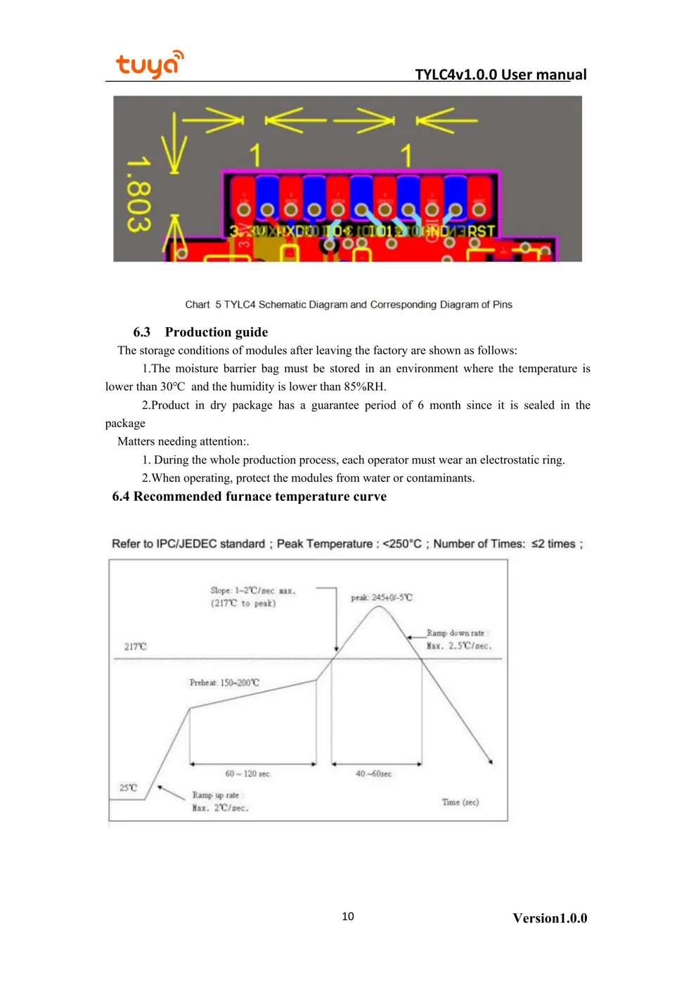
2.2 Pin definition
Version1.0.04
2. Module Interfaces
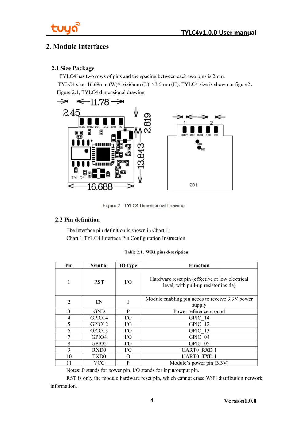
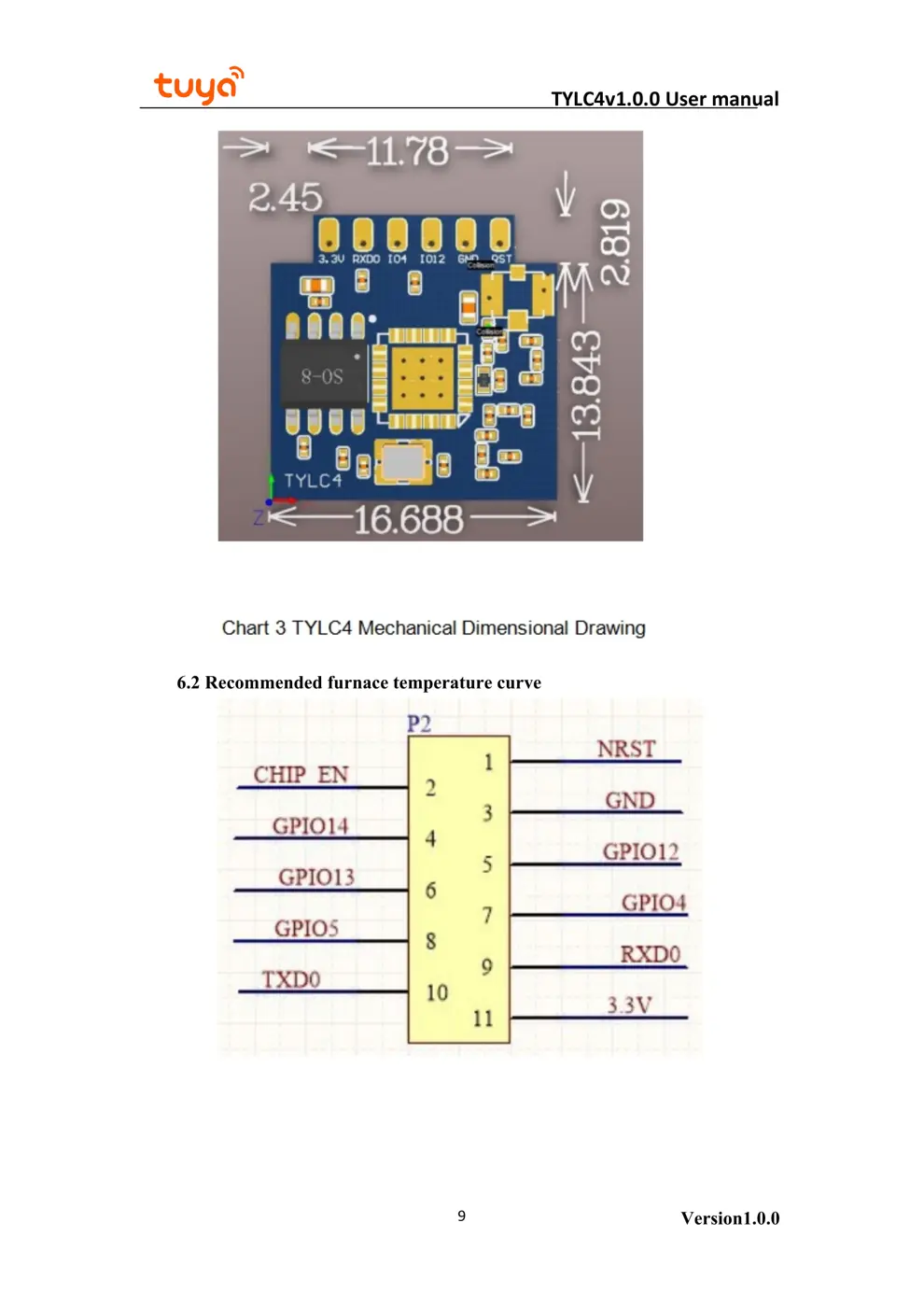
2.1 Size Package
TYLC4 has two rows of pins and the spacing between each two pins is 2mm.
TYLC4 size: 16.69mm (W)×16.66mm (L) ×3.5mm (H). TYLC4 size is shown in figure2:
Figure 2.1, TYLC4 dimensional drawing
The interface pin definition is shown in Chart 1:
Chart 1 TYLC4 Interface Pin Configuration Instruction
Table 2.1
,WR1 pins description
Pin Symbol IOType Function
1 RST I/O Hardware reset pin (effective at low electrical
level, with pull-up resistor inside)
2 EN I Module enabling pin needs to receive 3.3V power
supply
3 GND P Power reference ground
4 GPIO14 I/O
GPIO_14
5 GPIO12 I/O GPIO_12
6 GPIO13 I/O GPIO_13
7 GPIO4 I/O GPIO_04
8 GPIO5 I/O GPIO_05
9 RXD0 I/O UART0_RXD 1
10 TXD0 O UART0_TXD 1
11 VCC P Module’s power pin (3.3V)
Notes: P stands for power pin, I/O stands for input/output pin.
RST is only the module hardware reset pin, which cannot erase WiFi distribution network
information.
TYLC4v1.0.0 User manual
Version1.0.05
information output and user can ignore it.
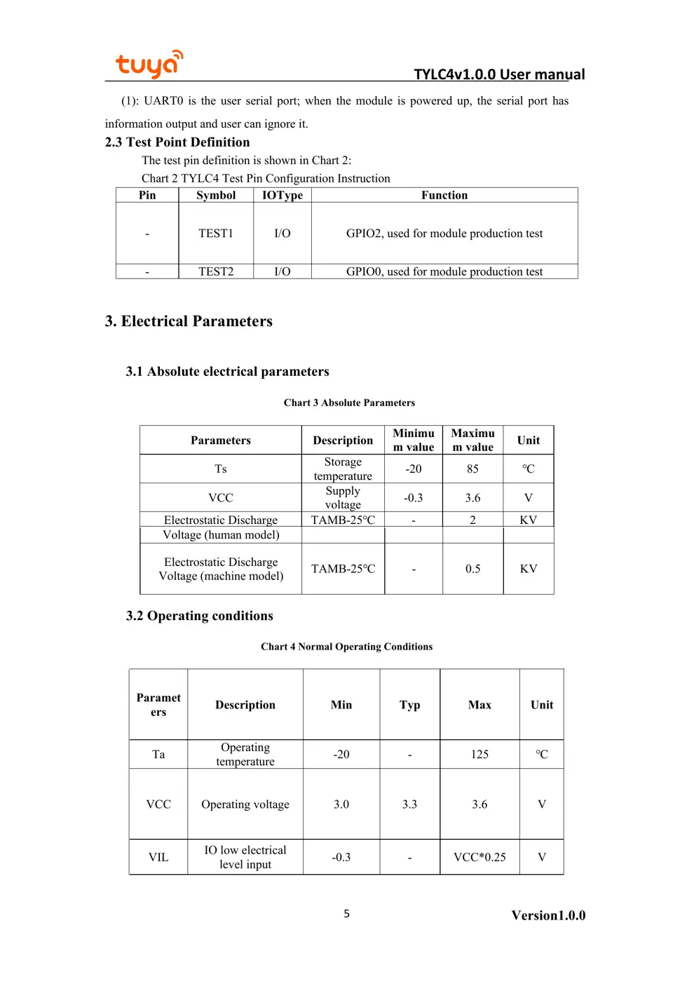
2.3 Test Point Definition
The test pin definition is shown in Chart 2:
Chart 2 TYLC4 Test Pin Configuration Instruction
Pin Symbol IOType Function
- TEST1 I/O GPIO2, used for module production test
- TEST2 I/O GPIO0, used for module production test
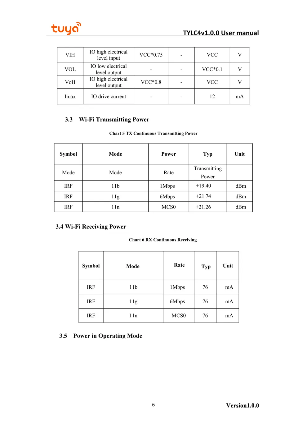
3. Electrical Parameters
3.1 Absolute electrical parameters
Chart 3 Absolute Parameters
Parameters Description Minimu
m value
Maximu
m value Unit
Ts Storage
temperature -20 85 ℃
VCC Supply
voltage -0.3 3.6 V
Electrostatic Discharge TAMB-25℃ - 2 KV
(1): UART0 is the user serial port; when the module is powered up, the serial port has
Voltage (human mod...