WR1 Reset & Teardown (FCC ID 2ANDL-WR1)
Factory reset and internal photos for Tuya Global WR1. Tuya / Smart Life smart plug.
January 15, 2026
•
9 read
Before you buy the Tuya Global WR1, check what's inside.
The WR1 is a low-power, compact Wi-Fi module designed by Tuya, featuring an ARM CM4F processor and an on-board PCB antenna. It's intended for integration into smart home devices and other IoT applications requiring Wi-Fi connectivity.
⚠️ NOTE: Ensure correct voltage is supplied. Handle with care to avoid static discharge.
Quick Specs
- Manufacturer: Tuya Global
- Model: WR1
- Protocol: WiFi
- Chipset: Realtek RTL8710
- Ecosystem: Tuya / Smart Life
- App: Smart Life
🔧 Geek Corner (Flashing Info)
- Chipset: W3021E75M2
- Flashable: ❌ No
- Info: The device uses a proprietary Tuya module with a specific chipset (W3021E75M2) and firmware that is not designed for custom flashing with open-source firmware like Tasmota or ESPHome.
User Manual
Scanned pages from the official user manual:
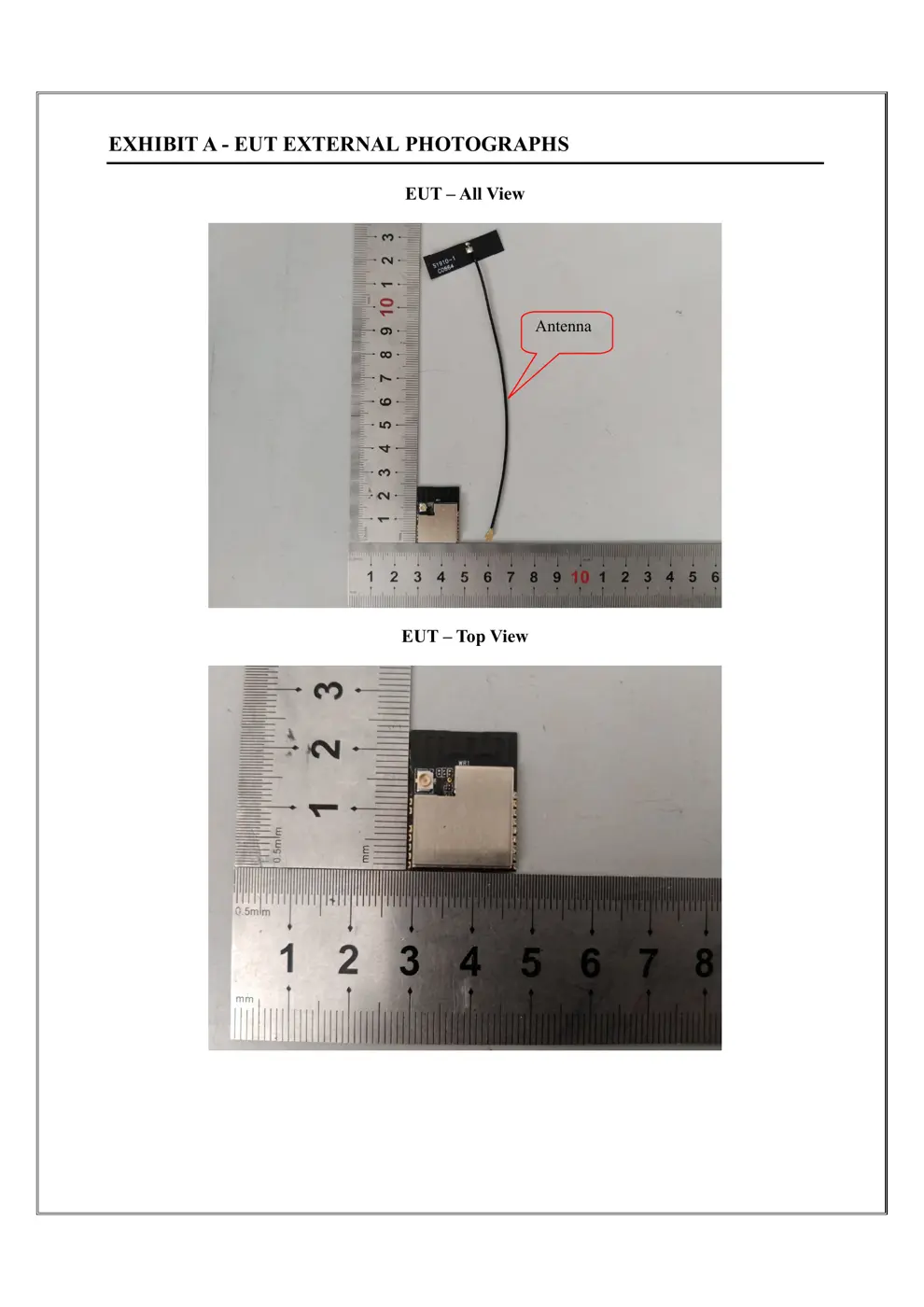
External Photos
Photos of the device exterior:
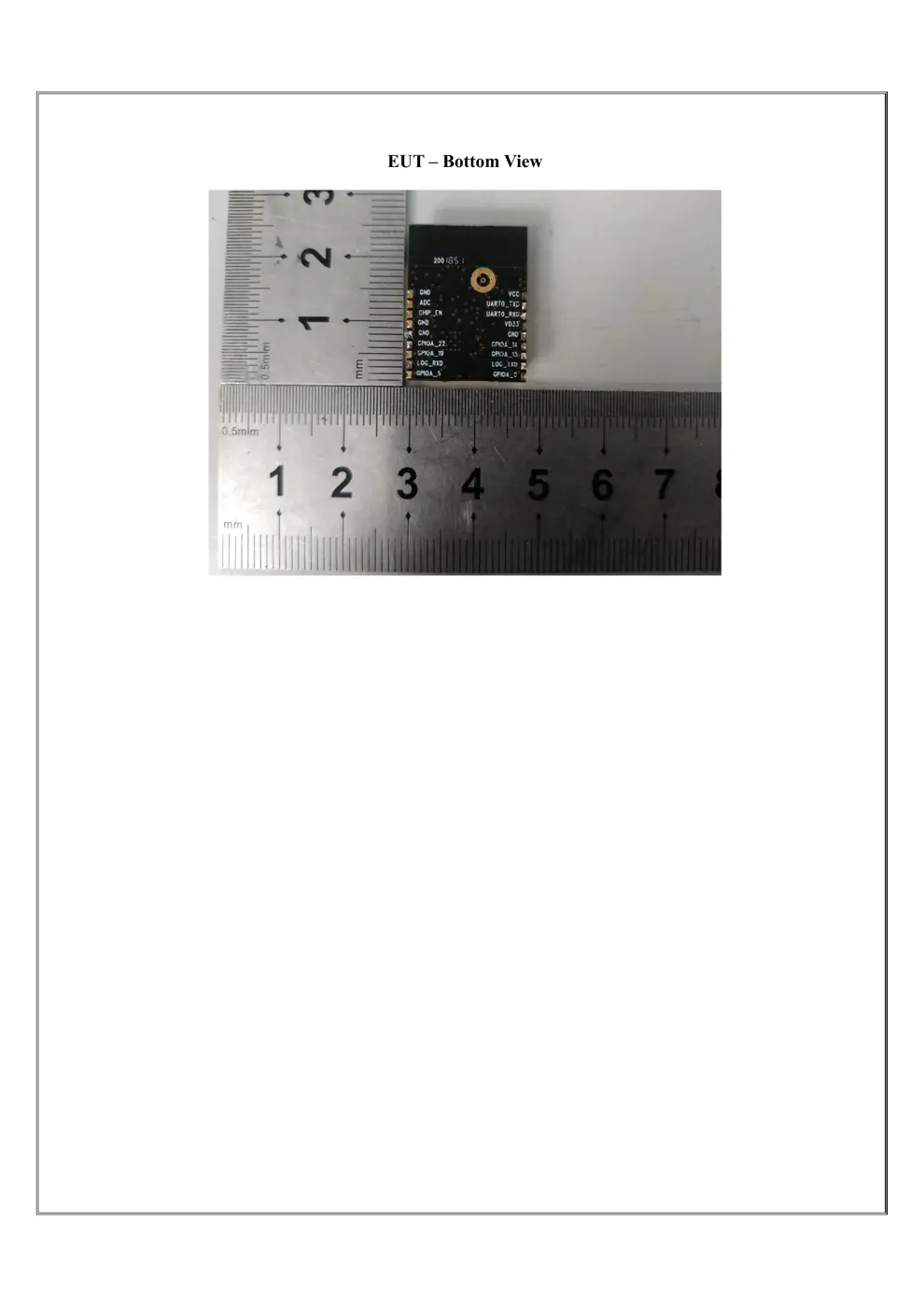
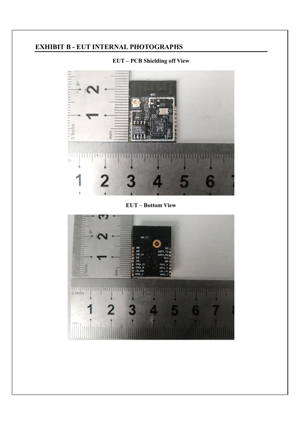
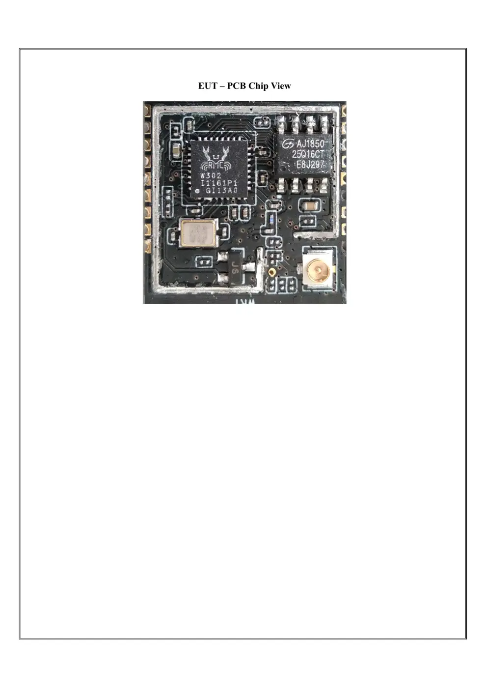
Internal Photos
Teardown photos showing the PCB and components:
Verdict
The WR1 is a WiFi device from the Tuya / Smart Life ecosystem.
📄 Click to view full text manual (SEO)
WR1DA
TASHEET
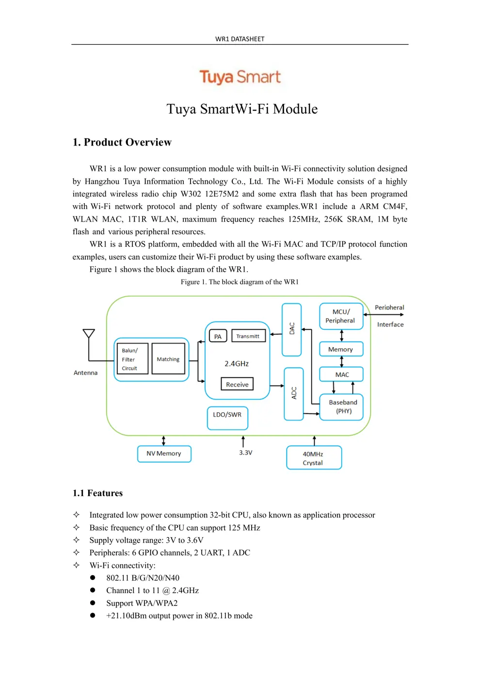
Tuya SmartWi-Fi Module
1. Product Overview
WR1 is a low power consumption module with built-in Wi-Fi connectivity solution designed
by Hangzhou Tuya Informatio n Technology Co., Ltd. Th e Wi-Fi Module consists o f a highly
integrated wireless radio chip W3 02 12E7 5M2 and some extra flash that has been programed
with Wi-Fi network protocol an d plenty of software examples.WR1 include a ARM CM4F,
WLAN MAC, 1T1R WLAN, maximum frequency reaches 125MHz, 256K SRAM, 1M byte
flash and vario us peripheral resources.
WR1 is a RTOS platform, embedded with all the Wi-Fi MAC and TCP/IP protocol function
examples, users can customize their Wi-Fi product by using these software examples.
Figure 1 shows the block diagram of the WR1.
Figure 1. The block diagram of the WR1
1.1 Features
Integrated low power consumption 32-bit CPU, also known as application processor
Basic frequency of the CPU can support 125 MHz
Supply voltage range: 3V to 3.6V
Peripherals: 6 GPIO channels, 2 UART, 1 ADC
Wi-Fi connectivity:
802.11 B/G/N20/N40
Channel 1 to 11 @ 2.4GHz
Support WPA/WPA2
+21.10dBm output power in 802.11b mode
WR1D
ATASHEET
Support SmartConfig function for both Android and IOS devices
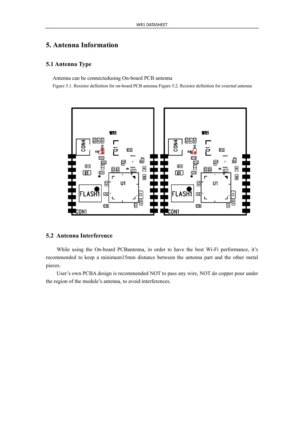
On-board PCB antenna
Operating temperature range: -20℃ to 105 ℃
1.2 Main Application Fields
Intelligent Building
Intelligent home, Intelligent household applications
Healthy devices
Industrial wireless control
Baby monitor
Webcam
Intelligent bus
WR1D
ATASHEET
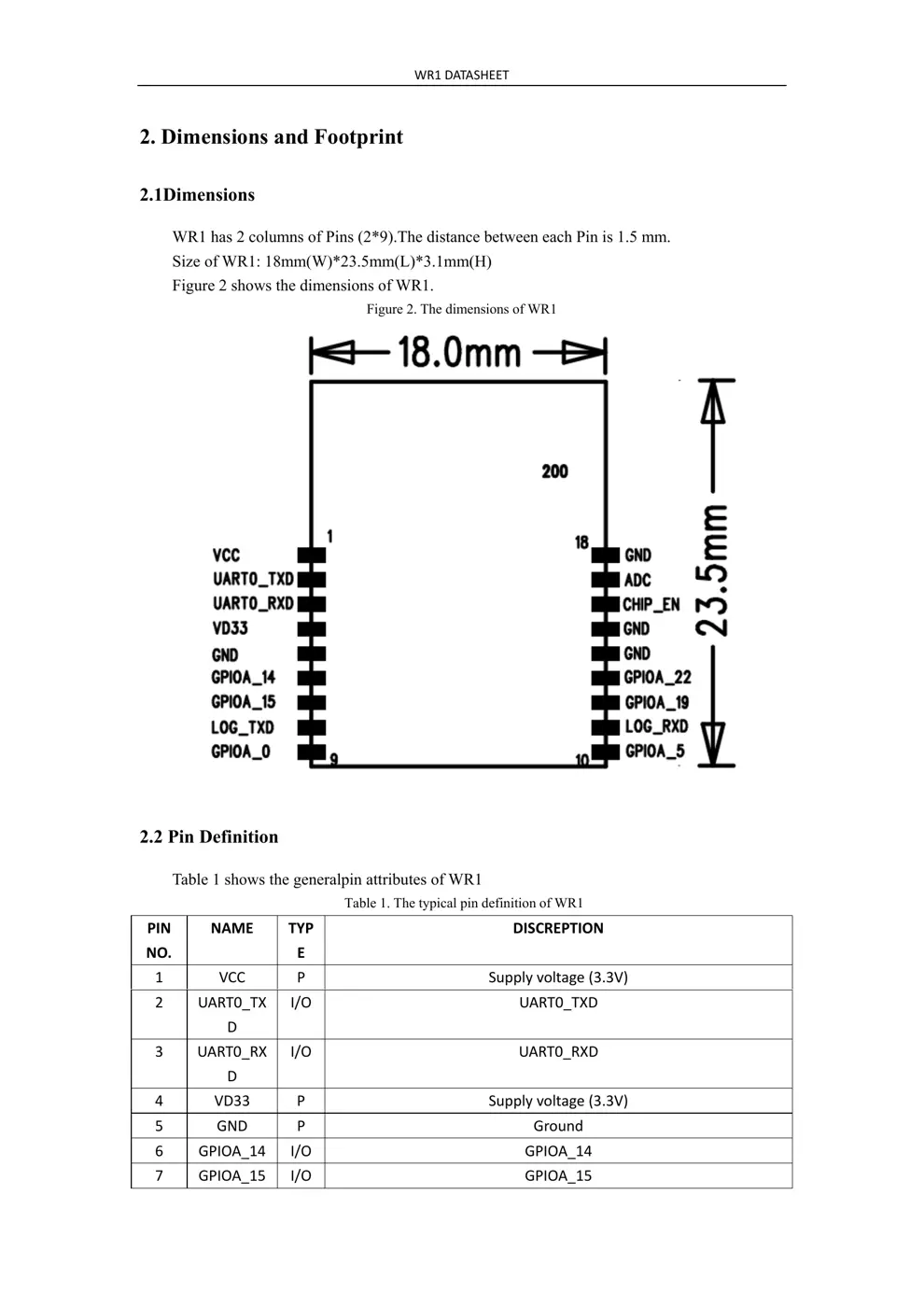
2. Dimensions and Footprint
2.1Dimensions
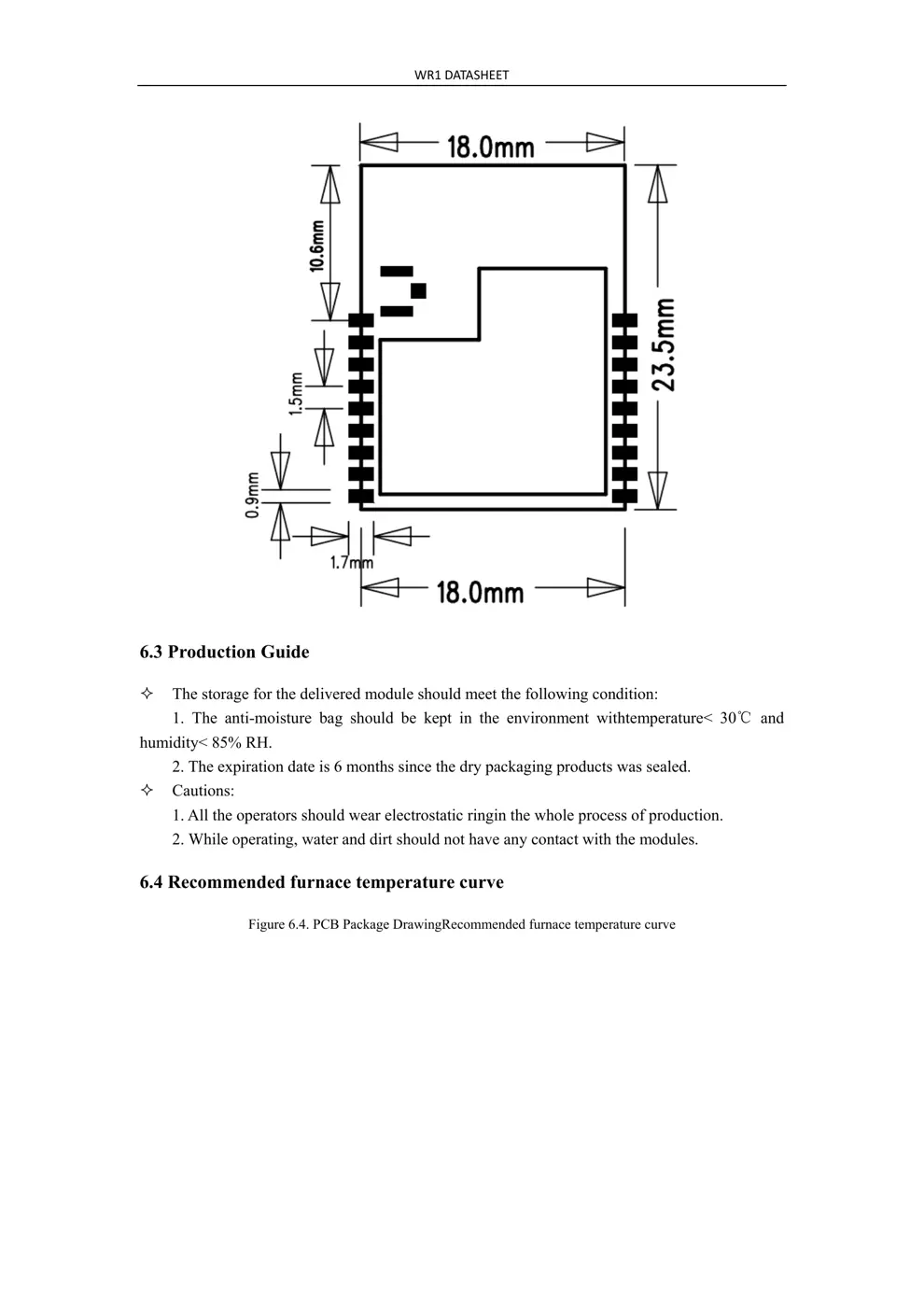
WR1 has 2 columns of Pins (2*9).The distance between each Pin is 1.5 mm.
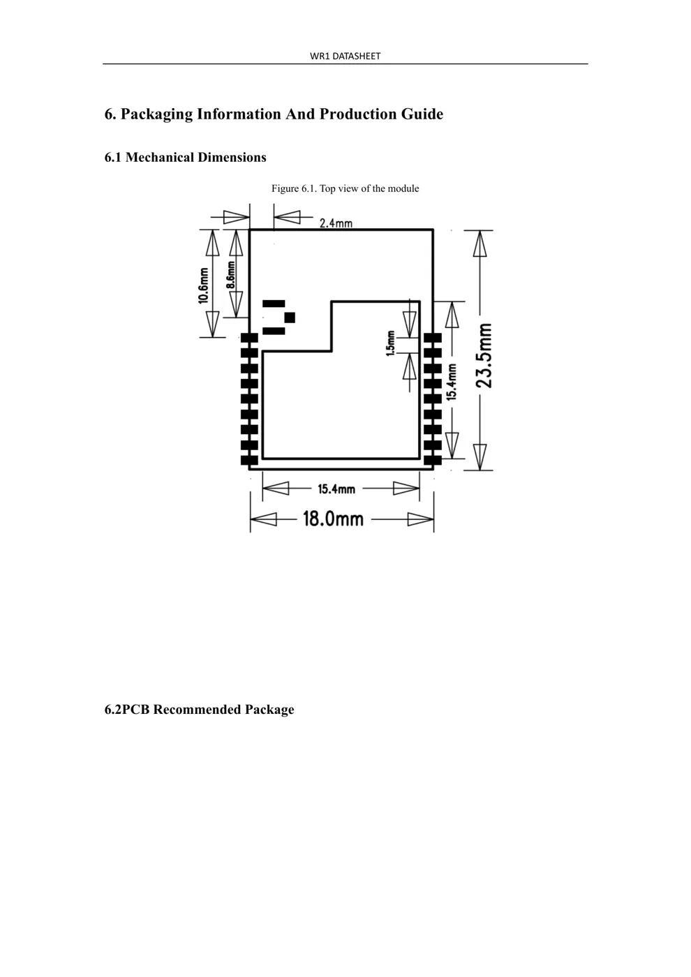
Size of WR1: 18mm(W)*23.5mm(L)*3.1mm(H)
Figure 2 shows the dimensions of WR1.
Figure 2. The dimensions of WR1
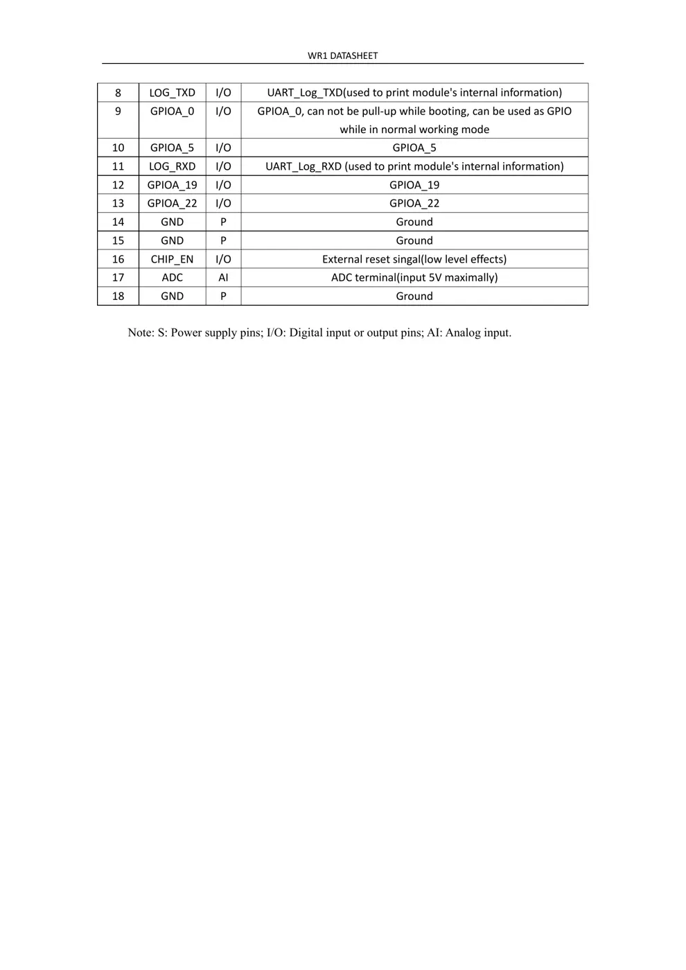
2.2 Pin Definition
Table 1 shows the generalpin attributes of WR1
Table 1. The typical pin definition of WR1
PIN
NO.
NAME TYP
DISCREPTION
1 VC
C P Supplyvoltage(3.3V)
2 UA
RT0_TX
I/O UART0_TXD
3 UA
RT0_RX
I/O UART0_RXD
4 VD33 P Supplyvo
ltage(3.3V)
5 GND P Gr
ound
6 GPIO
A_14 I/O GPIOA_14
7 GPIO
A_15 I/O GPIOA_15
WR1D
ATASHEET
8 LO
G_TXD I/O UART_Log_TXD(usedtoprintmodule'sinternalinformation)
9 GPIO
A_0 I/O GPIOA_0,cannotbepull‐upwhilebooting,canbeusedasGPIO
whileinnormalworkingmode
10 GPIO
A_5 I/O GPIOA_5
11 LO
G_RXD I/O UART_Log_RXD(usedtoprintmodule'sinternalinformation)
12 GPIO
A_19 I/O GPIOA_19
13 GPIO
A_22 I/O GPIOA_22
14 GND P Gr
ound
15 GND P Gr
ound
16 CHIP_EN I/O Ex
ternalresetsingal(lowleveleffects)
17 ADC AI ADCt
erminal(input5Vmaximally)
18 GND P Gr
ound
N
ote: S: Power supply pins; I/O: Digital input or output pins; AI: Analog input.
WR1D
ATASHEET
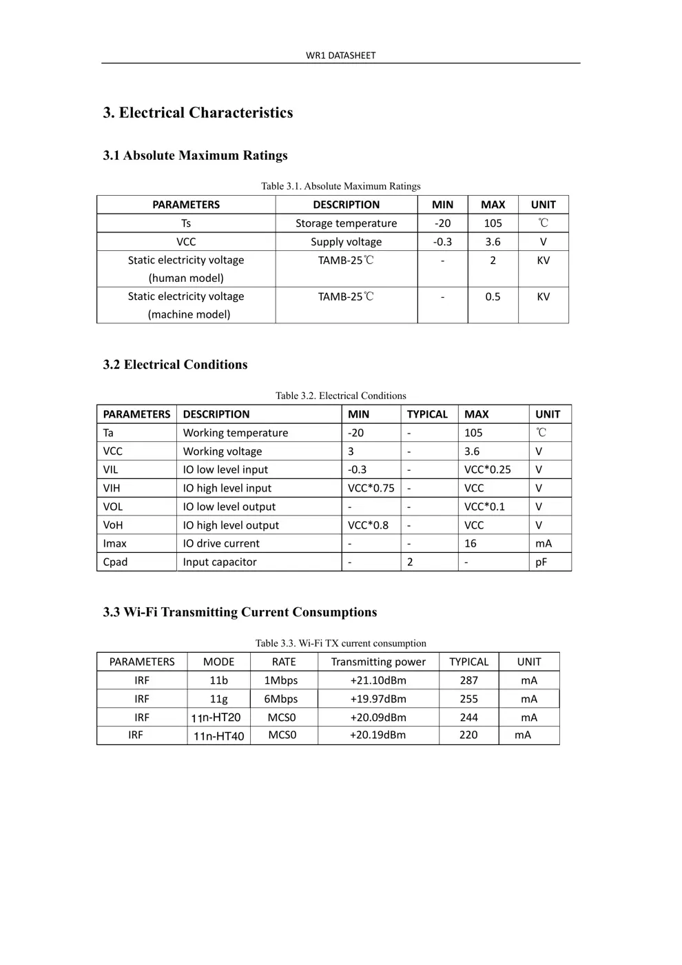
3. Electrical Characteristics
3.1
Absolute Maximum Ratings
T
able 3.1. Absolute Maximum Ratings
PA
RAMETERS DESCRIPTION MIN MAX UNIT
Ts St
oragetemperature‐ 20 105 ℃
VC
C Supplyvoltage ‐0.3 3.6 V
St
aticelectricityvoltage
(humanmodel)
TAMB‐25℃ ‐ 2 KV
St
aticelectricityvoltage
(machinemodel)
TAMB‐25℃ ‐ 0.5 KV
3.2 Electrical Conditions
T
able 3.2. Electrical Conditions
PA
RAMETERS DESCRIPTION MIN...