WR1E Reset & Teardown (FCC ID 2ANDL-WR1E)
Factory reset and internal photos for Tuya Global WR1E. Tuya / Smart Life smart plug.
January 15, 2026
•
9 read
Before you buy the Tuya Global WR1E, check what's inside.
The WR1E is a low-power Wi-Fi module designed for integration into smart home devices, featuring a 32-bit ARM CM4F CPU and supporting 802.11 b/g/n connectivity. It is intended for use in applications requiring wireless control and data transmission.
⚠️ NOTE: Ensure correct voltage (3V-3.6V) is supplied to the VCC pin. Do not exceed the absolute maximum supply voltage of 3.6V.
Quick Specs
- Manufacturer: Tuya Global
- Model: WR1E
- Protocol: WiFi
- Chipset: Realtek RTL8710
- Ecosystem: Tuya / Smart Life
- App: Smart Life
🔧 Geek Corner (Flashing Info)
- Chipset: W302 HB140P1
- Flashable: ❌ No
- Info: The WR1E module is part of the Tuya ecosystem and typically uses proprietary firmware. While it contains a capable ARM CM4F chip, it's not designed for easy flashing of custom firmware like Tasmota or ESPHome without significant reverse engineering or specialized tools.
User Manual
Scanned pages from the official user manual:
External Photos
Photos of the device exterior:
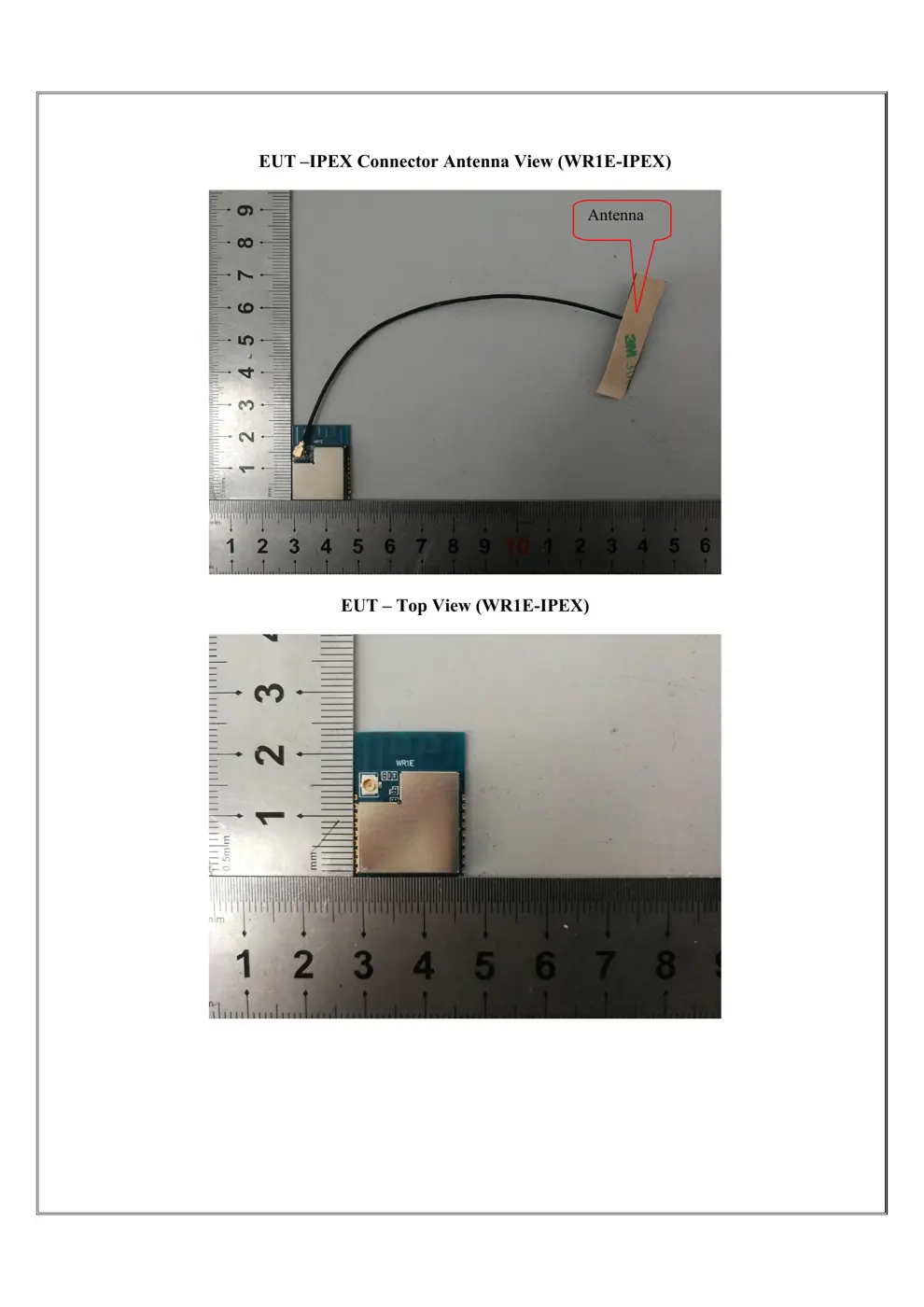
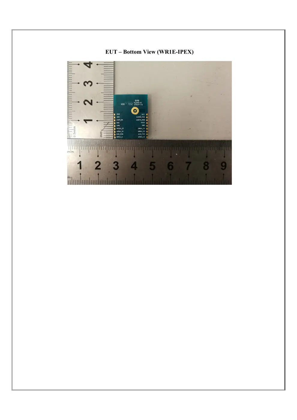
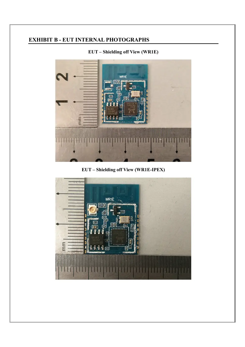
Internal Photos
Teardown photos showing the PCB and components:
Verdict
The WR1E is a WiFi device from the Tuya / Smart Life ecosystem.
📄 Click to view full text manual (SEO)
WR1E User Manual
TuyaSmartWi-Fi Module
1. Product Overview
WR1E is a low power consumption module with bu ilt-in Wi-Fi connectivity
solution designed by Hangzhou Tuya Information Technology Co., Ltd. The Wi-Fi Module
consists of a highly
integrated wireless radio chip W302 HB140P1 and some extra flash that
has been programed with Wi-Fi network protocol and plenty of software examples.WR1E
include a ARM
CM4F, WLAN MAC, 1T1R WLAN, maximum frequency reaches
125MHz, 256K SRAM, 1M byte flash and various peripheral resources.
WR1E is a RTOS platform, embedded with all the Wi-Fi MAC and TCP/IP protocol function
examples, users can customize their Wi-Fi product by using these software examples.
1.1 Features
Integrated low power consumption 32-bit CPU, also known as application processor
Basic frequency of the CPU can support 125 MHz
Supply voltage range: 3V to 3.6V
Peripherals:6 GPIO channels, 2 UART, 1 ADC
Wi-Fi connectivity:
802.11 B/G/N20/N40
Channel 1 to 11 @ 2.4GHz
Support WPA/WPA2
Support SmartConfig function for both Android and IOS devices
On-board PCB antenna and U.FLRFconnectorexternalantenna
Pass CE, FCC, SRRC certifications
Operating temperature range: -20℃ to 85℃
1.2 Main Application Fields
Intelligent Building
Intelligent home, Intelligent household applications
Healthy devices
Industrial wireless control
Baby monitor
Webcam
Intelligent bus
WR1E User Manual
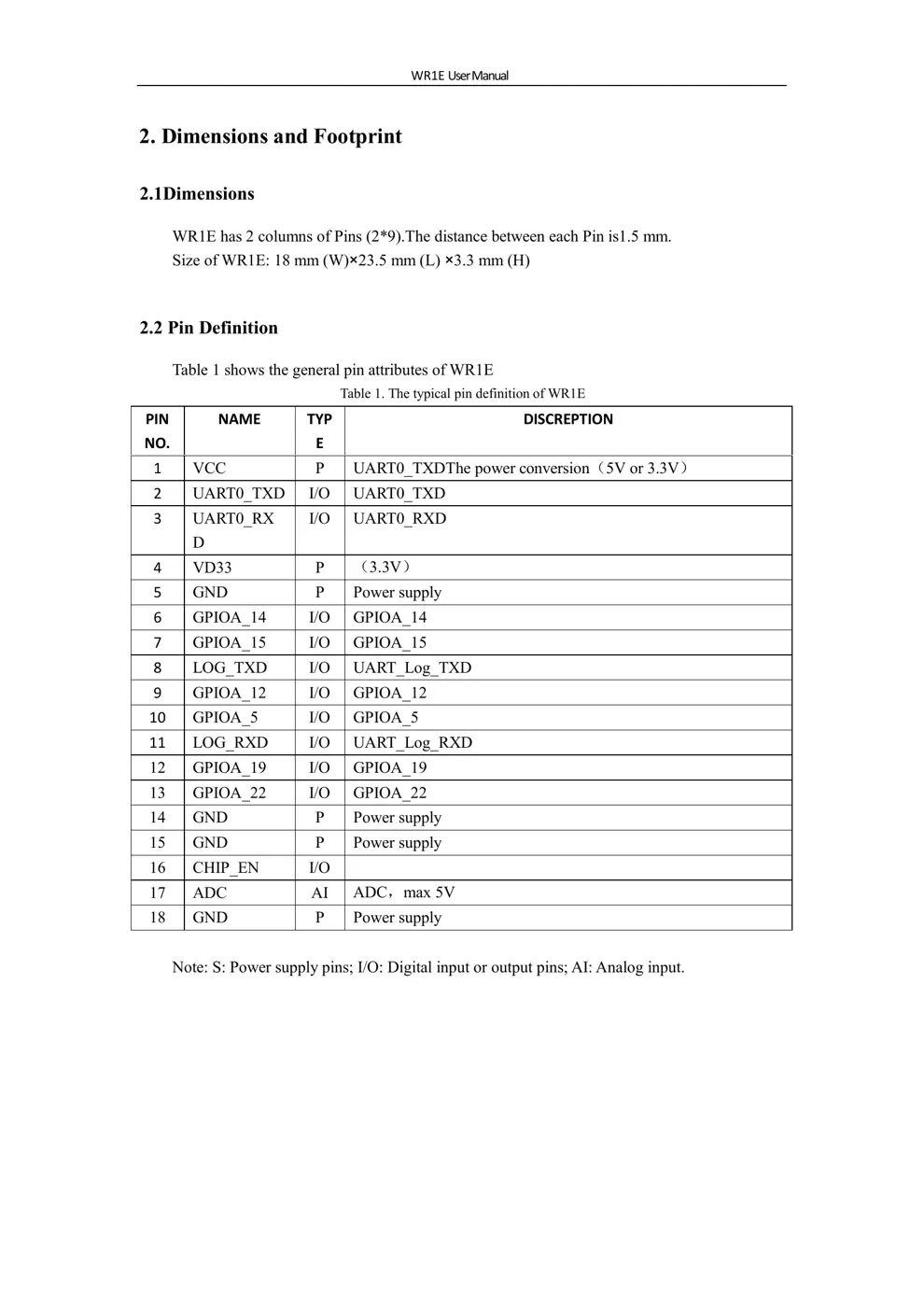
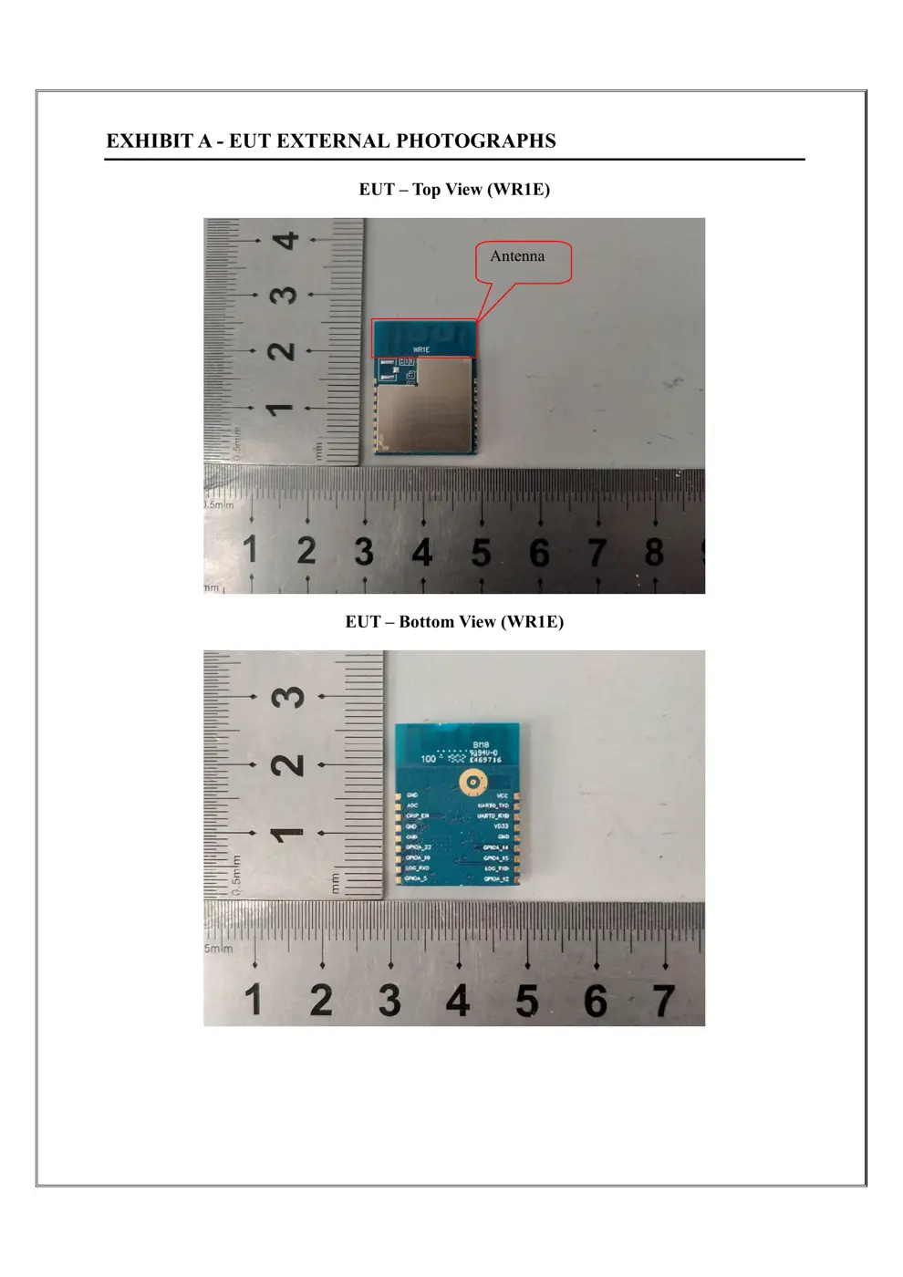
2. Dimensions and Footprint
2.1Dimensions
WR1E has 2 columns of Pins (2*9).The distance between each Pin is1.5 mm.
Size of WR1E: 18 mm (W)×23.5 mm (L) ×3.3 mm (H)
2.2 Pin Definition
Table 1 shows the general pin attributes of WR1E
Table 1. The typical pin definition of WR1E
PIN
NO.
NAME TYP
E
DISCREPTION
1 VCC P UART0_TXDThe power conversion(5V or 3.3V)
2 UART0_TXD I/O UART0_TXD
3 UART0_RX
D
I/O UART0_RXD
4 VD33 P (3.3V)
5 GND P Power supply
6 GPIOA_14 I/O GPIOA_14
7 GPIOA_15 I/O GPIOA_15
8 LOG_TXD I/O UART_Log_TXD
9 GPIOA_12 I/O GPIOA_12
10 GPIOA_5 I/O GPIOA_5
11 LOG_RXD I/O UART_Log_RXD
12 GPIOA_19 I/O GPIOA_19
13 GPIOA_22 I/O GPIOA_22
14 GND P Power supply
15 GND P Power supply
16 CHIP_EN I/O
17 ADC AI ADC,max 5V
18 GND P Power supply
Note: S: Power supply pins; I/O: Digital input or output pins; AI: Analog input.
WR1E User Manual
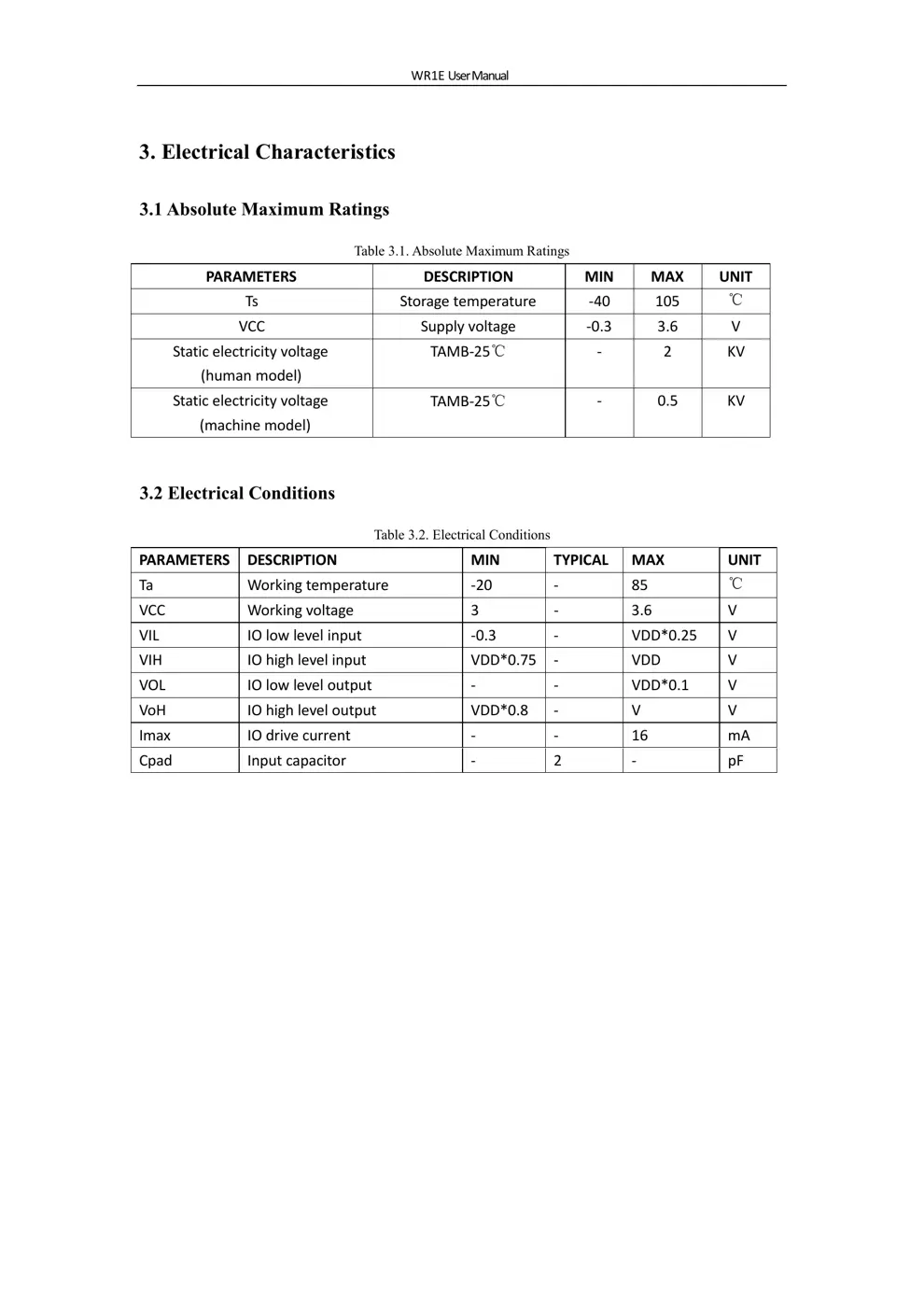
3. Electrical Characteristics
3.1 Absolute Maximum Ratings
Table 3.1. Absolute Maximum Ratings
PARAMETERS DESCRIPTION MIN MAX UNIT
Ts Storagetemperature ‐40 105 ℃
VCC Supplyvoltage ‐0.3 3.6 V
Staticelectricityvoltage
(humanmodel)
TAMB‐25℃ ‐ 2 KV
Staticelectricityvoltage
(machinemodel)
TAMB‐25℃ ‐ 0.5 KV
3.2 Electrical Conditions
Table 3.2. Electrical Conditions
PARAMETERS DESCRIPTION MIN TYPICAL MAX UNIT
Ta Workingtemperature ‐20 ‐ 85 ℃
VCC Workingvoltage 3 ‐ 3.6 V
VIL IOlowlevelinput ‐0.3 ‐ VDD*0 .2 5 V
VIH IOhighlevelinput VDD*0.7 5 ‐ VDD V
VOL IOlowleveloutput ‐ ‐ VDD*0. 1 V
VoH IOhighleveloutput VDD*0.8 ‐ V V
Imax IOdrivecurrent ‐ ‐ 16 mA
Cpad Inputcapacitor ‐ 2 ‐ pF
WR1E User Manual
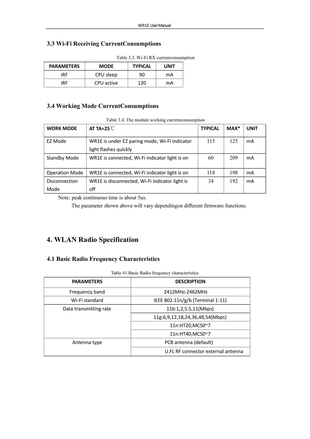
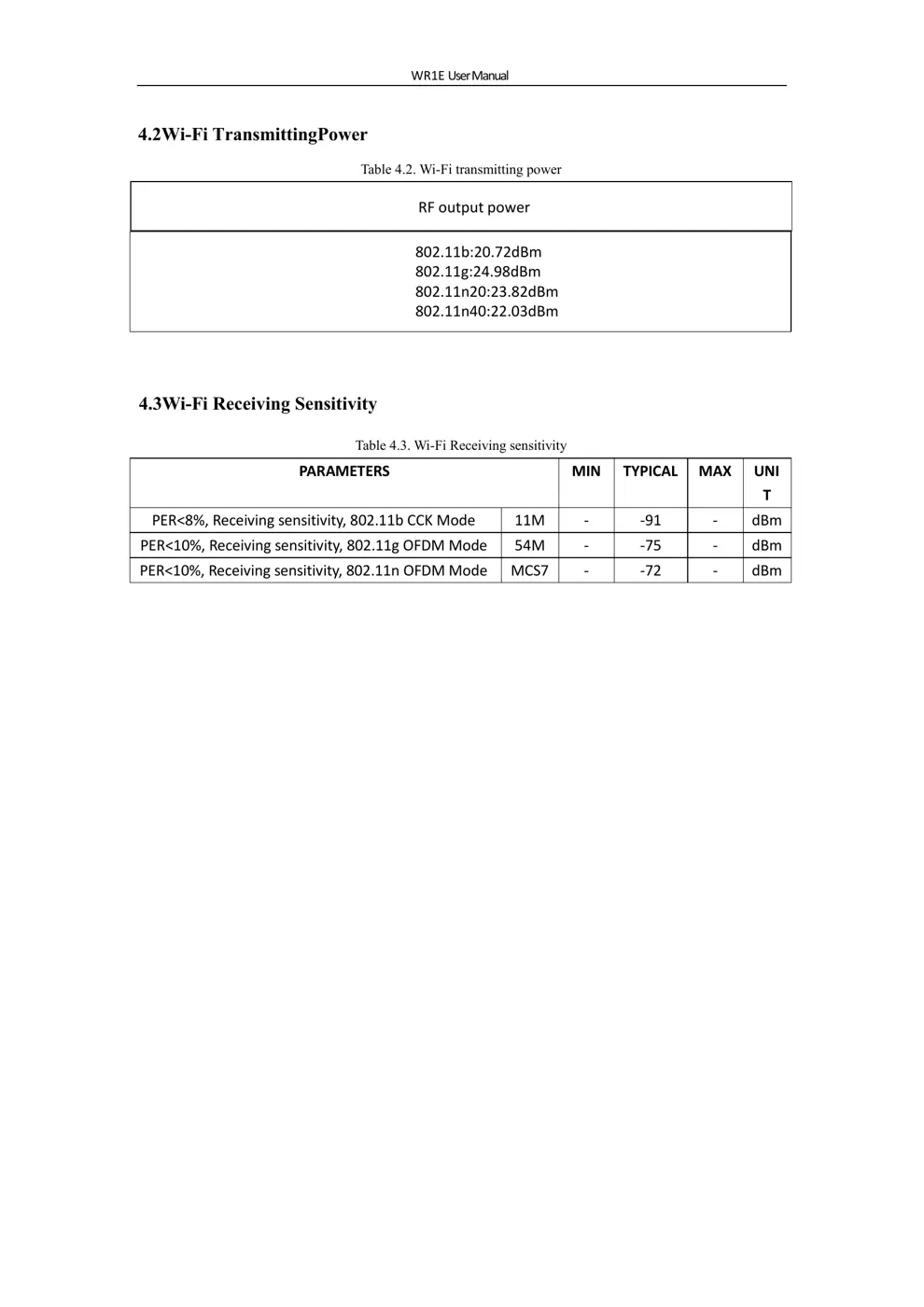
3.3 Wi-Fi ...