WR3LE Reset & Teardown (FCC ID 2ANDL-WR3LE)
Factory reset and internal photos for Tuya Global WR3LE. Tuya / Smart Life smart plug.
Before you buy the Tuya Global WR3LE, check what's inside.
The Tuya WR3LE is a compact, low-power Wi-Fi module based on the RTL8710BX chipset, designed for integration into various smart home and IoT devices. It supports standard 802.11 b/g/n connectivity and operates within a 3-3.6V range, making it suitable for battery-powered applications.
⚠️ NOTE: Ensure the module is powered within the specified 3-3.6V range and handle with care to avoid static discharge.
Quick Specs
- Manufacturer: Tuya Global
- Model: WR3LE
- Protocol: WiFi
- Chipset: Beken BK7231N
- Ecosystem: Tuya / Smart Life
- App: Smart Life
🔧 Geek Corner (Flashing Info)
- Chipset: RTL8710BX
- Flashable: ❌ No
- Info: The RTL8710BX chipset often has locked bootloaders or proprietary firmware that prevents easy flashing of custom firmware like Tasmota or ESPHome. While the device lists 'OpenBeken' and 'flashable: true' in the original metadata, specific community reports for the RTL8710BX variant of WR3LE suggest limited or no success with flashing.
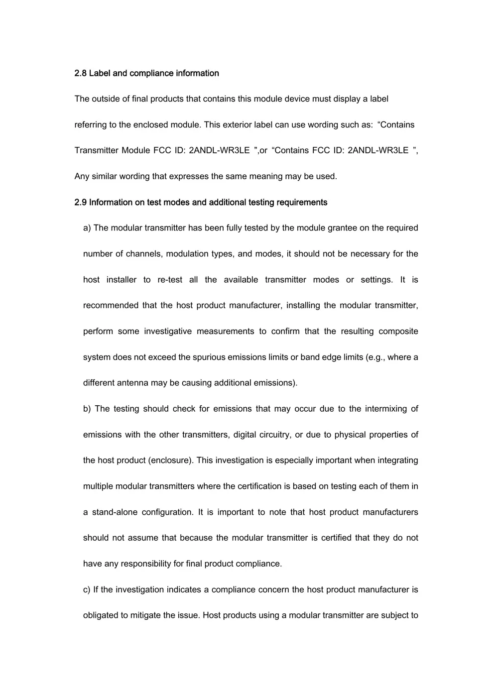
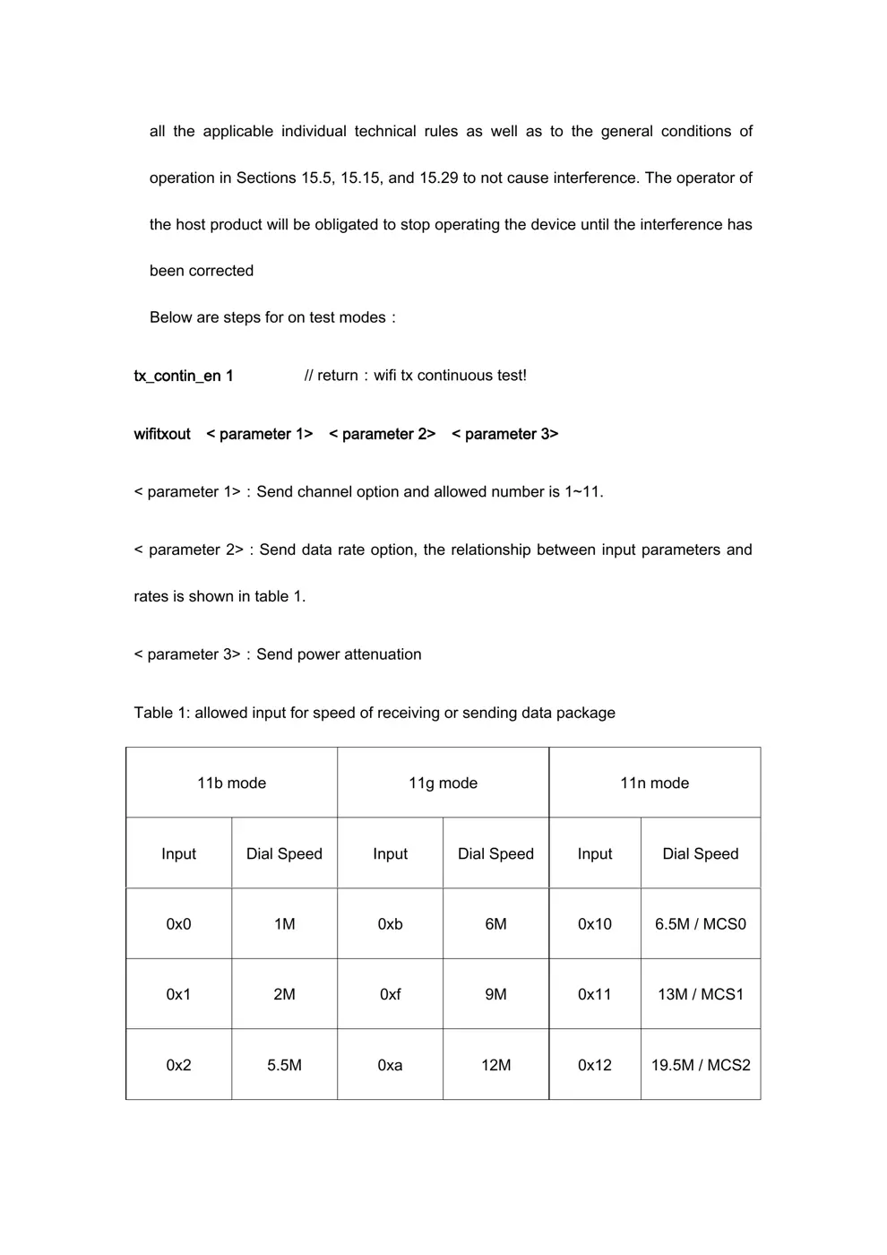
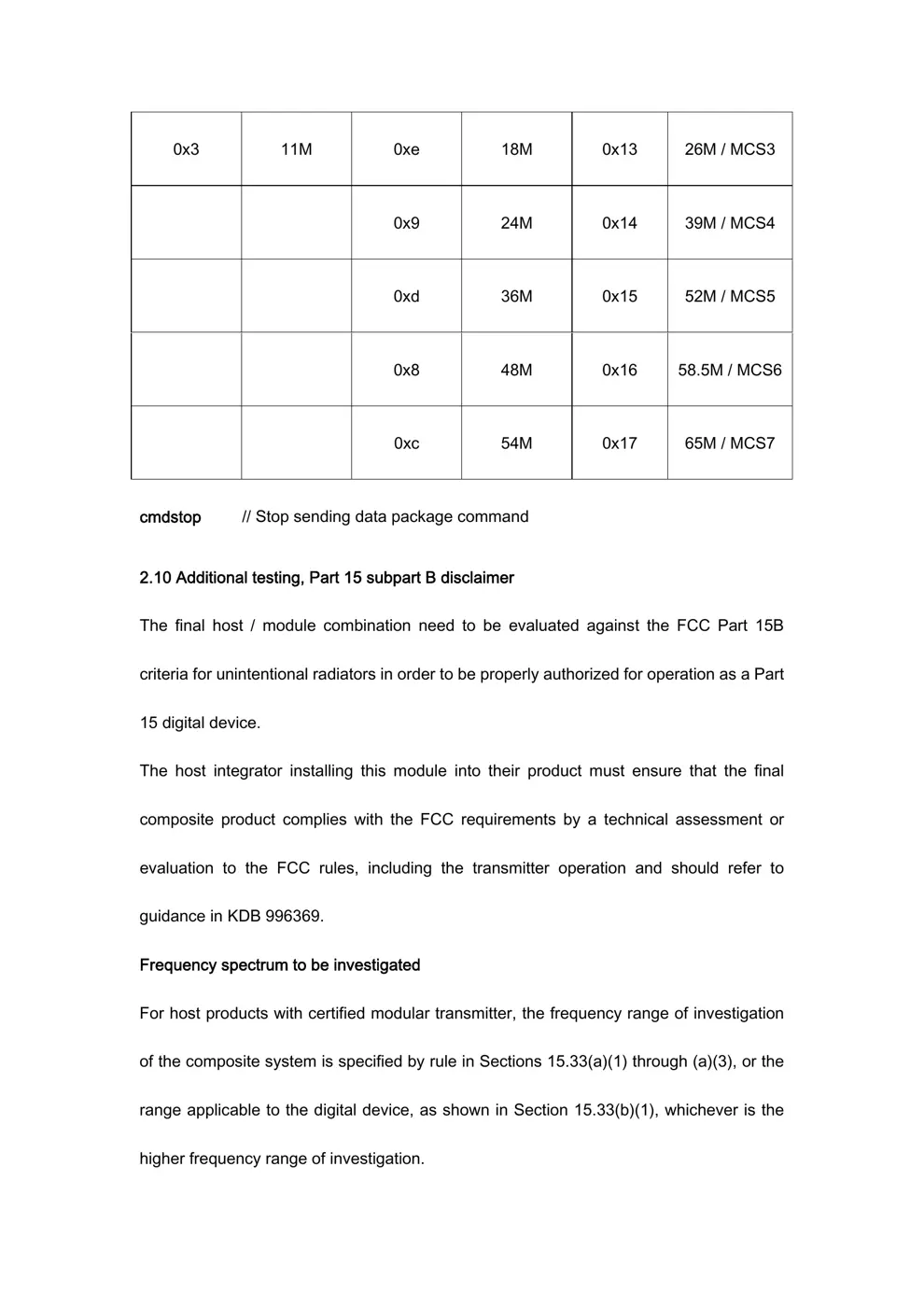
User Manual
Scanned pages from the official user manual:
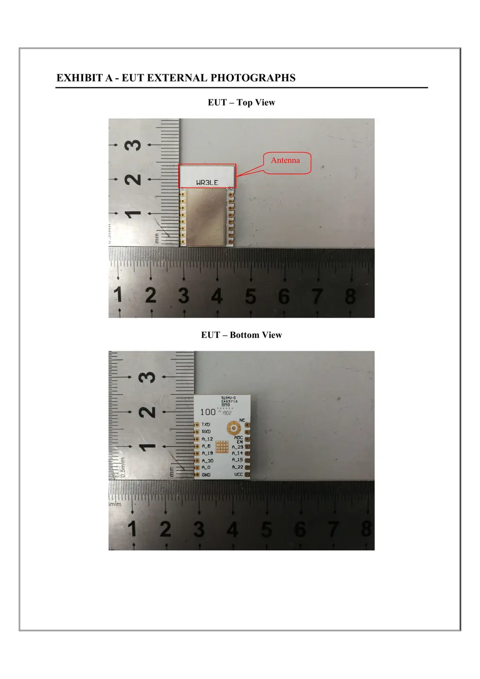
External Photos
Photos of the device exterior:
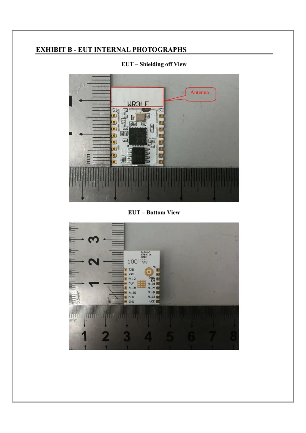
Internal Photos
Teardown photos showing the PCB and components:
Verdict
The WR3LE is a WiFi device from the Tuya / Smart Life ecosystem.
📄 Click to view full text manual (SEO)
WR3LE User Manual
TuyaSmartWi-Fi Module
1. Product Overview
WR3LE is a low power consumption module with built-in Wi-Fi connectivity solution
designed by Hangzhou Tuya Information
Technology Co.,Ltd. The Wi-Fi Module consists of a
highly integrated wireless radio chip RTL8710BX and some extra flash that has been programed
with Wi-Fi network protocol and plenty of software examples.WR 3LE include a ARM CM4F,
WLAN MAC, 1T1R WLAN, maximum frequency reaches 125MHz, 256K SRAM, 2Mbyte
flash and various peripheral resources.
WR3LE is a RTOS
platform, embedded with all the Wi -Fi MAC and TCP/IP protocol
function examples, users can customize their Wi-Fi product by using these software examples.
1.1 Features
Integrated low power consumption 32-bit CPU, also known as application processor
Basic frequency of the CPU can support 125 MHz
Supply voltage range: 3V to 3.6V
Peripherals:7 GPIO channels, 2 UART, 1 ADC
Wi-Fi connectivity:
802.11 B/G/N20/N40
Channel 1 to 11@ 2.4GHz
Support WPA/WPA
2
Support Smart Config function for both Android and IOS devices
On-board PCB antenna
Pass CE, FCC, SRRC certifications
Operating temperature range: -20℃ to105℃
1.2 Main ApplicationFields
Intelligent Building
Intelligent home, Intelligent household applications
Healthy devices
Industrial wireless control
Baby monitor
Webcam
Intelligent bus
WR3LE User Manual
2. Dimensions and Footprint
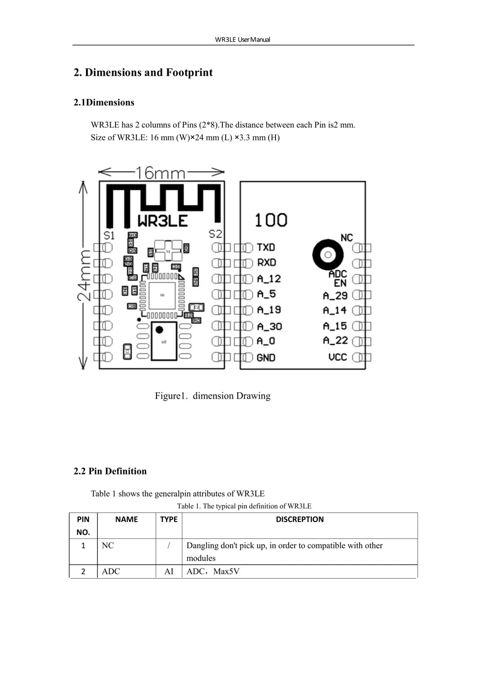
2.1Dimensions
WR3LE has 2 columns of Pins (2*8).The distance between each Pin is2 mm.
Size of WR3LE: 16 mm (W)×24 mm (L) ×3.3 mm (H)
2.2 Pin Definition
Table 1 shows the generalpin attributes of WR3LE
Table 1. The typical pin definition of WR3LE
PIN
NO.
NAME TYPE DISCREPTION
1 NC / Dangling don't pick up, in order to compatible with other
modules
2 ADC AI ADC,Max5V
Figure1. dimension Drawing
WR3LE User Manual
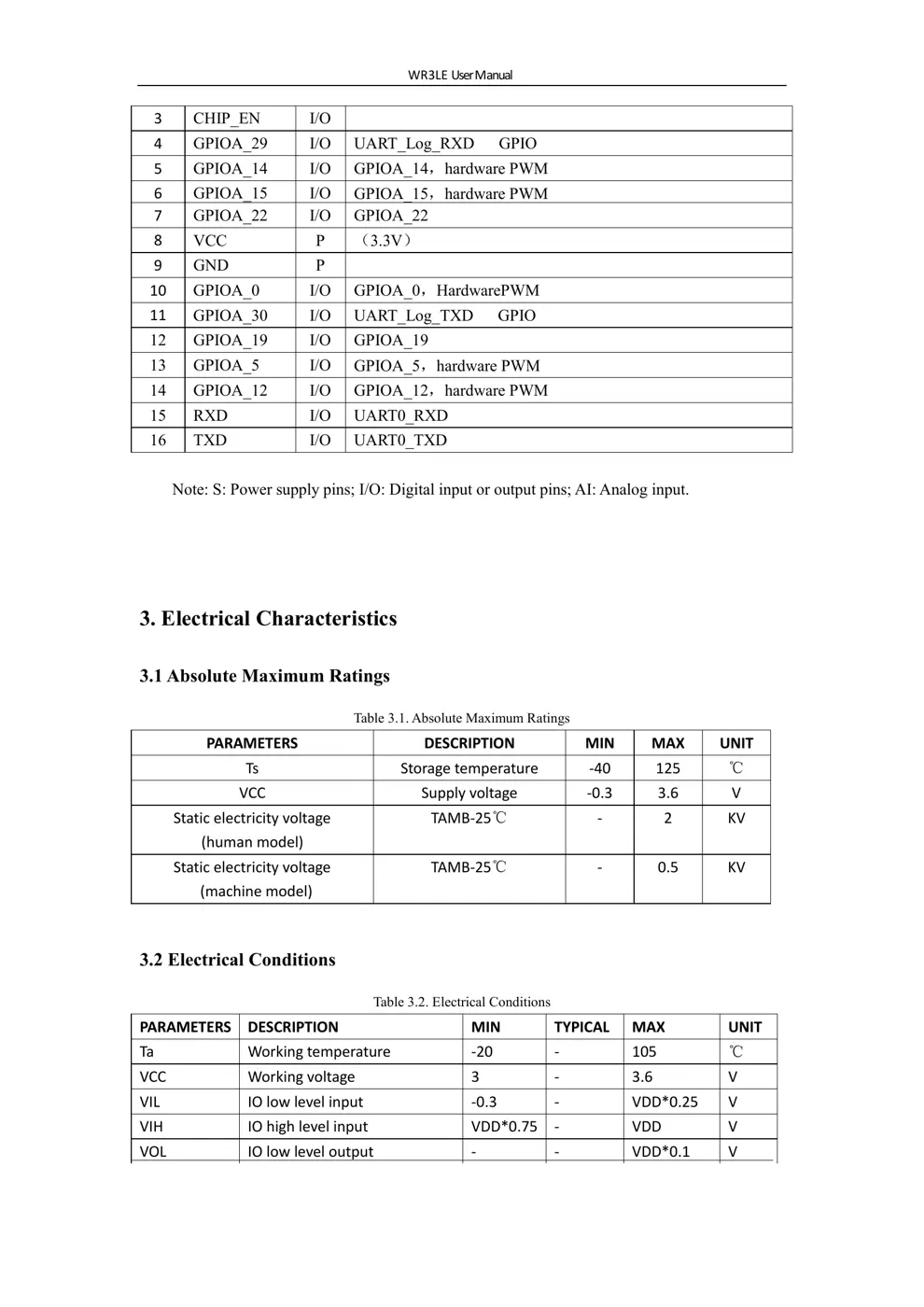
3. Electrical Characteristics
3.1 Absolute Maximum Ratings
Table 3.1. Absolute Maximum Ratings
PARAMETERS DESCRIPTION MIN MAX UNIT
Ts Storage temperature -40 125 ℃
VCC Supply voltage -0.3 3.6 V
Static electricity voltage
(human model)
TAMB-25℃ - 2 KV
Static electricity voltage
(machine model)
TAMB-25℃ - 0.5 KV
3.2 Electrical Conditions
Table 3.2. Electrical Conditions
PARAMETERS DESCRIPTION MIN TYPICAL MAX UNIT
Ta Working temperature -20 - 105 ℃
VCC Working voltage 3 - 3.6 V
VIL IO low level input -0.3 - VDD*0.25 V
VIH IO high level input VDD*0.75 - VDD V
VOL IO low level output - - VDD*0.1 V
7 GPIOA_22 I/O GPIOA_22
8 VCC P (3.3V)
9 GND P
10 GPIOA_0 I/O GPIOA_0,HardwarePWM
11 GPIOA_30 I/O UART_Log_TXD GPIO
12 GPIOA_19 I/O GPIOA_19
13 GPIOA_5 I/O GPIOA_5,hardware PWM
14 GPIOA_12 I/O GPIOA_12,hardware PWM
15 RXD I/O UART0_RXD
16 TXD I/O UART0_TXD
Note: S: Power supply pins; I/O: Digital input or output pins; AI: Analog input.
3 CHIP_EN I/O
4 GPIOA_29 I/O UART_Log_RXD GPIO
5 GPIOA_14 I/O GPIOA_14,hardware PWM
6 GPIOA_15 I/O GPIOA_15,hardware PWM
WR3LE User Manual
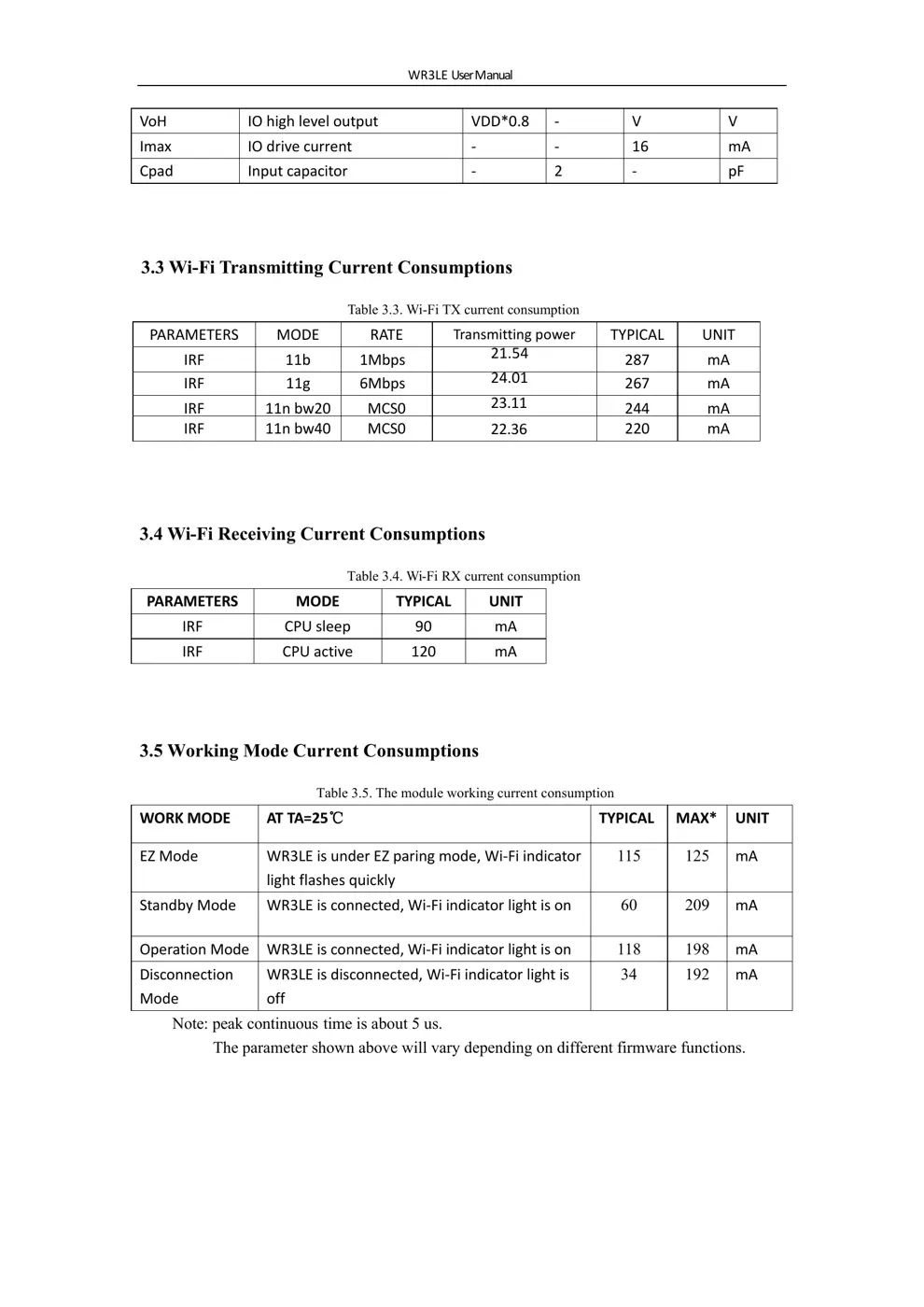
3.4 Wi-Fi Receiving Current Consumptions
Table
...