WRD8P Reset & Teardown (FCC ID 2ANDL-WRD8P)
Factory reset and internal photos for Tuya Global WRD8P. Tuya / Smart Life smart plug.
January 15, 2026
•
9 read
Before you buy the Tuya Global WRD8P, check what's inside.
The WRD8P is a low-power embedded Wi-Fi module developed by Tuya, featuring an Arm Cortex-M4 MCU and an RDA5981BM RF chip for smart home applications. It supports 802.11b/g/n connectivity and is designed for integration into various smart devices.
⚠️ NOTE: Requires a stable 3.3V power supply. Ensure proper voltage regulation before connecting.
Quick Specs
- Manufacturer: Tuya Global
- Model: WRD8P
- Protocol: WiFi
- Chipset: Realtek/Beken
- Ecosystem: Tuya / Smart Life
- App: Smart Life
🔧 Geek Corner (Flashing Info)
- Chipset: RDA5981BM
- Flashable: ❌ No
- Info: Proprietary Tuya module, likely locked down and not designed for third-party firmware.
User Manual
Scanned pages from the official user manual:

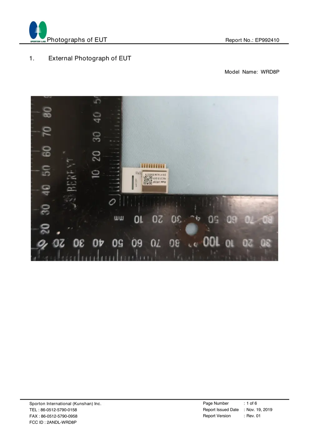
External Photos
Photos of the device exterior:

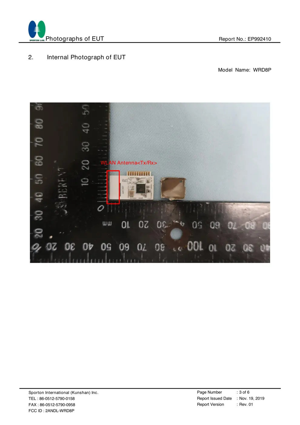
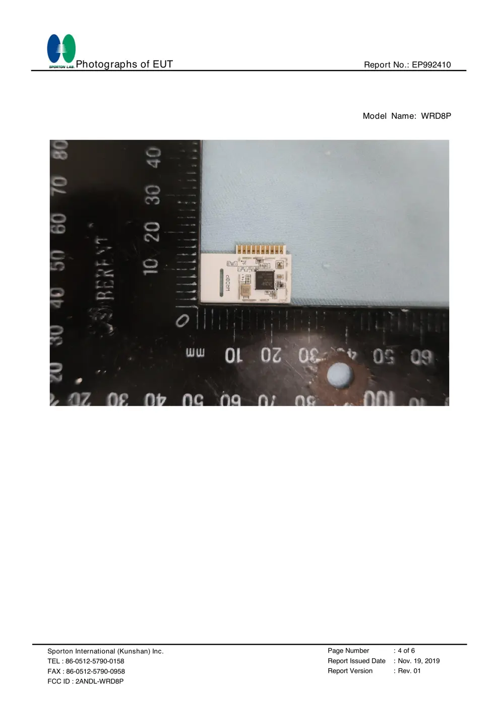
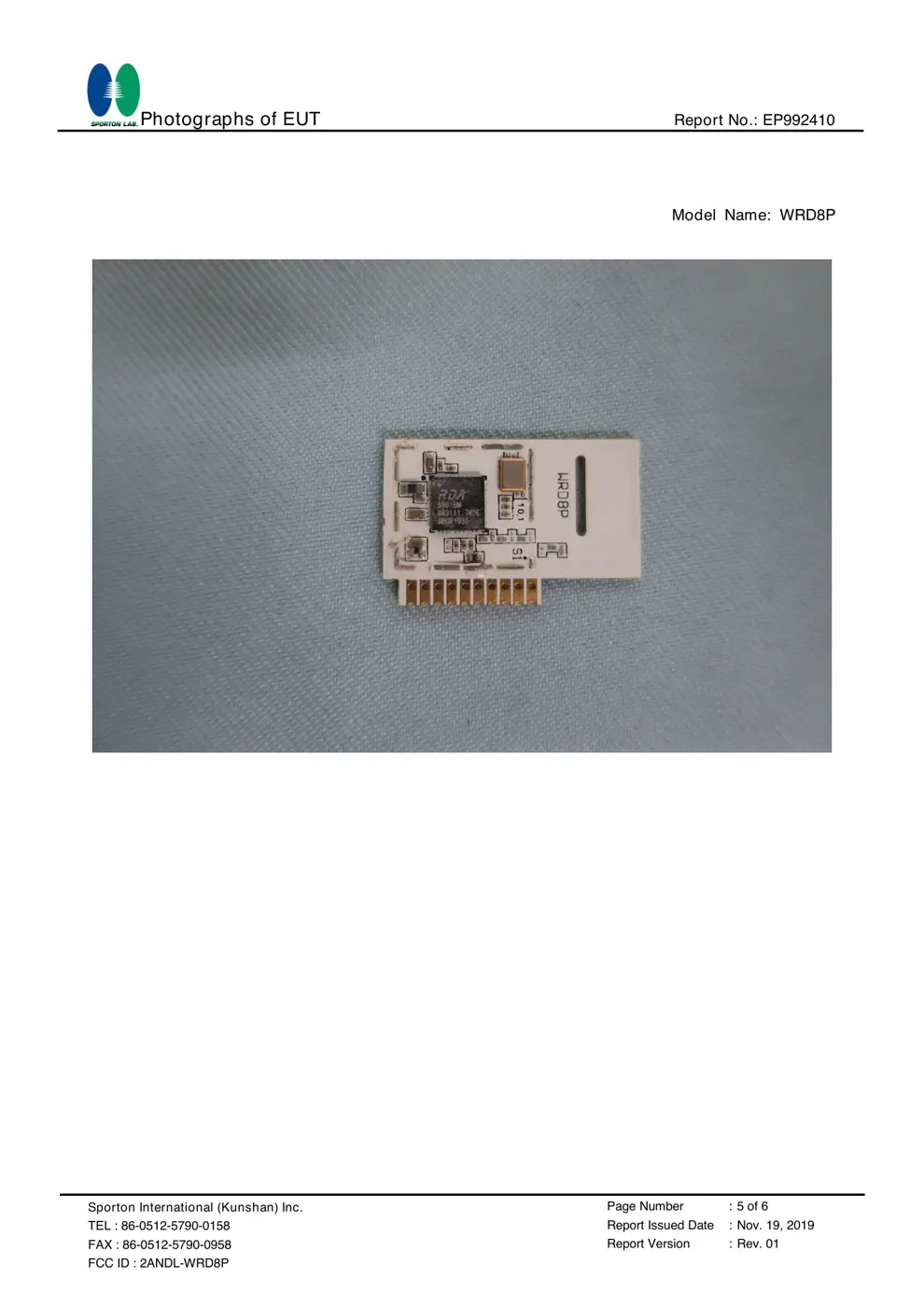
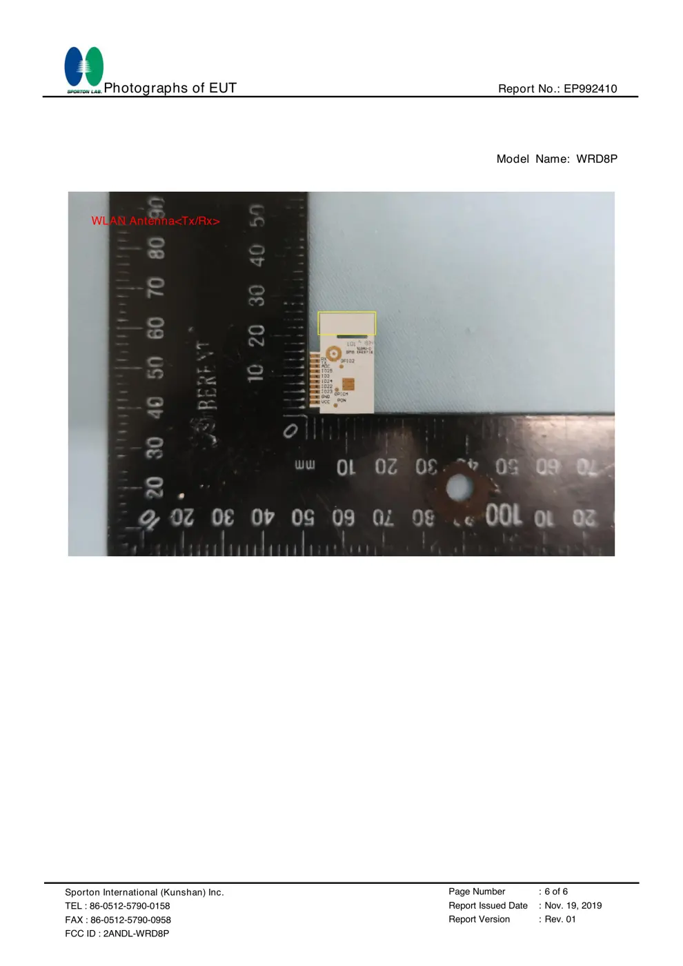
Internal Photos
Teardown photos showing the PCB and components:
Verdict
The WRD8P is a WiFi device from the Tuya / Smart Life ecosystem.
📄 Click to view full text manual (SEO)
1
WRD8P Datasheet
Product
Manual
Tuya WRD8P Wi-Fi Module
Version: 2.0.0 Date: 2019-09-18 No.:
Global Intelligent Platform
3.3 V input
Wi-Fi module
2 MB
flash SPI Arm
Cortex-
M4
MCU
802.11b/g/n
HT20
26 MHz
crystal
oscillator
Interface
3.3 V TTL
UART
5 x PWMs
1 x ADC
384 KB
SRAM
2.4 GHz
radio PCB
antenna
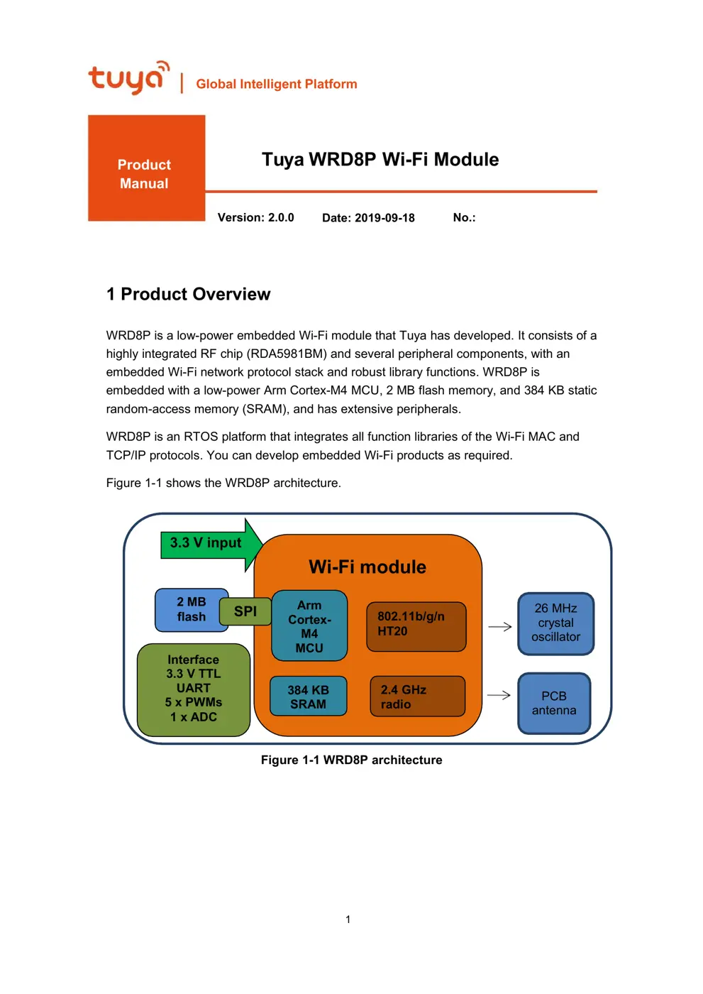
1 Product Overview
WRD8P is a low-power embedded Wi-Fi module that Tuya has developed. It consists of a
highly integrated RF chip (RDA5981BM) and several peripheral components, with an
embedded Wi-Fi network protocol stack and robust library functions. WRD8P is
embedded with a low-power Arm Cortex-M4 MCU, 2 MB flash memory, and 384 KB static
random-access memory (SRAM), and has extensive peripherals.
WRD8P is an RTOS platform that integrates all function libraries of the Wi-Fi MAC and
TCP/IP protocols. You can develop embedded Wi-Fi products as required.
Figure 1-1 shows the WRD8P architecture.
Figure 1-1 WRD8P architecture
2
WRD8P Datasheet
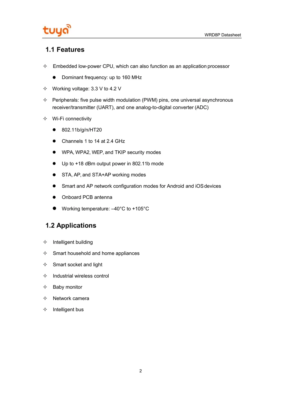
1.1 Features
Embedded low-power CPU, which can also function as an application processor
Dominant frequency: up to 160 MHz
Working voltage: 3.3 V to 4.2 V
Peripherals: five pulse width modulation (PWM) pins, one universal asynchronous
receiver/transmitter (UART), and one analog-to-digital converter (ADC)
Wi-Fi connectivity
802.11b/g/n/HT20
Channels 1 to 14 at 2.4 GHz
WPA, WPA2, WEP, and TKIP security modes
Up to +18 dBm output power in 802.11b mode
STA, AP, and STA+AP working modes
Smart and AP network configuration modes for Android and iOS devices
Onboard PCB antenna
Working temperature: –40°C to +105°C
1.2 Applications
Intelligent building
Smart household and home appliances
Smart socket and light
Industrial wireless control
Baby monitor
Network camera
Intelligent bus
3
WRD8P Datasheet
Change History
No. Date Change Description Version After Change
1 2019-07-18 This is the first release. 1.0.0
2 2019-09-18 Updated the ADC input voltage and
production instructions.
2.0.0
4
WRD8P Datasheet
Contents
1 Product Overview..........................................................................................................................1
1.1 Features.............................................................................................................................. 2
1.2 Applications........................................................................................................................ 2
2 Module Interfaces......................................................................................................................... 6
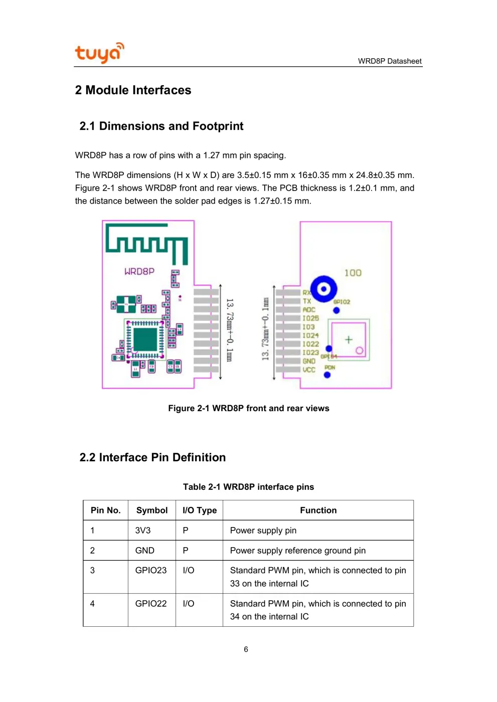
2.1 Dimensions and Footprint................................................................................................ 6
2.2 Interface Pin Definition..................................................................................................... 6
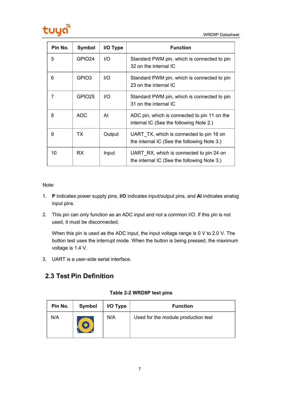
2.3 Test Pin Definition..............................................................................................................7
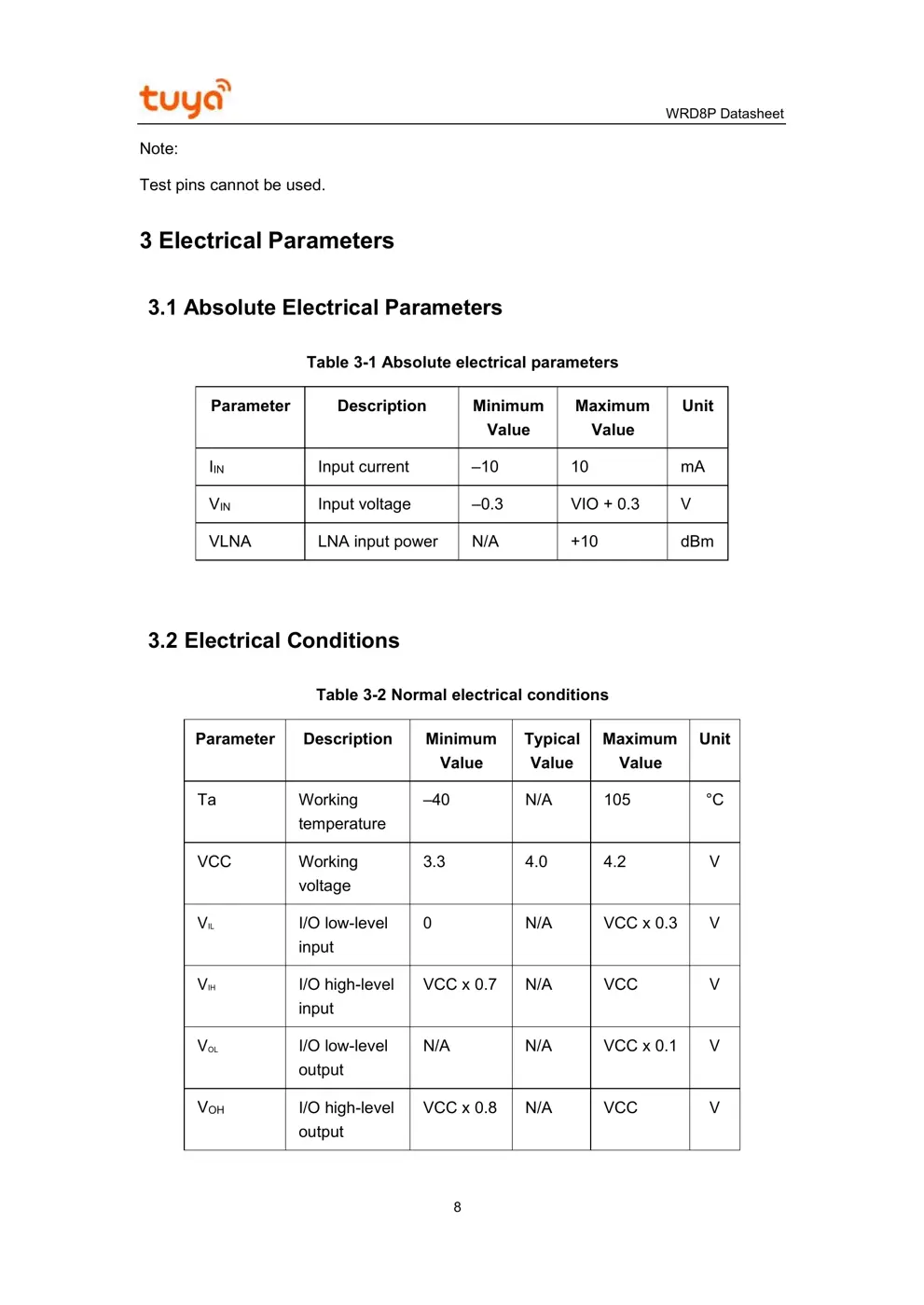
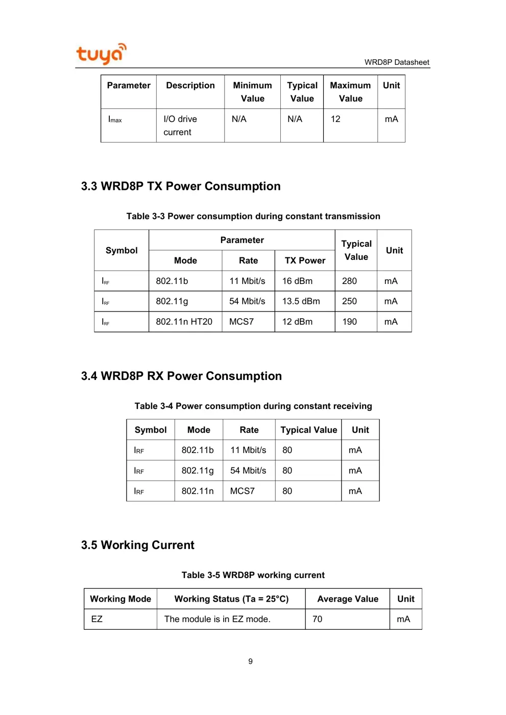
3 Electrical Parameters................................