ESP12S Reset & Teardown (FCC ID 2AHMRESP12S)
Factory reset and internal photos for Tuya OEM ESP12S. Tuya / Smart Life smart plug.
January 15, 2026
•
9 read
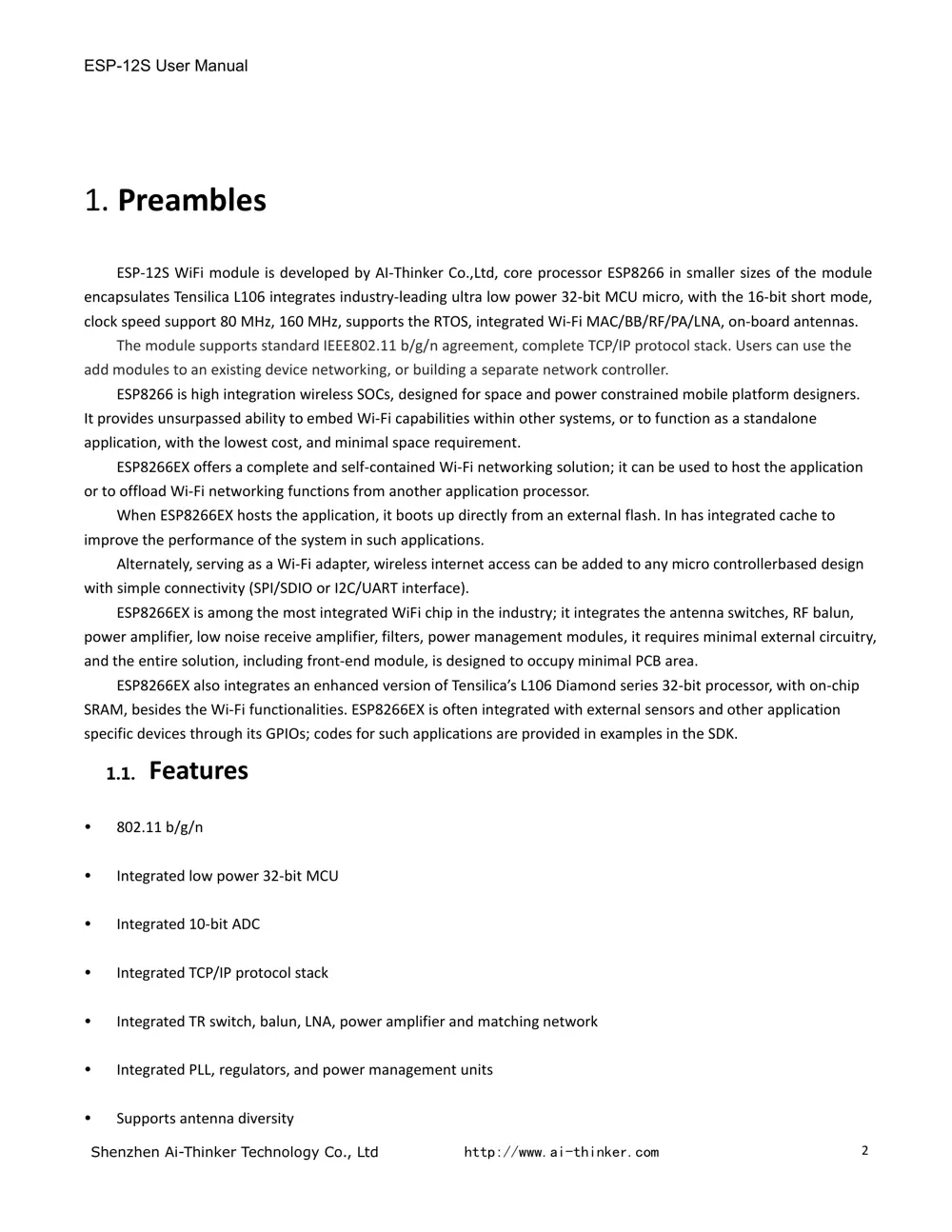
Before you buy the Tuya OEM ESP12S, check what's inside.
This is an ESP-12S module from Ai-Thinker, primarily used for DIY IoT projects. It's a WiFi-enabled microcontroller module based on the ESP8285 chip, commonly integrated into Tuya-compatible devices.
⚠️ NOTE: Handle with care during soldering and integration. Ensure proper power supply (typically 5V DC) and consider ESD protection.
Quick Specs
- Manufacturer: Tuya OEM
- Model: ESP12S
- Protocol: WiFi
- Chipset: ESP8266
- Ecosystem: Tuya / Smart Life
- App: Smart Life
🔧 Geek Corner (Flashing Info)
- Chipset: ESP8285
- Flashable: ✅ Yes
- Info: Based on the ESP8285 chip, it is known to be flashable with custom firmware like Tasmota or ESPHome.
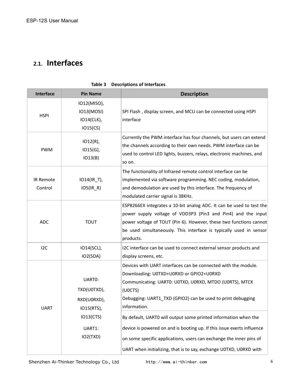
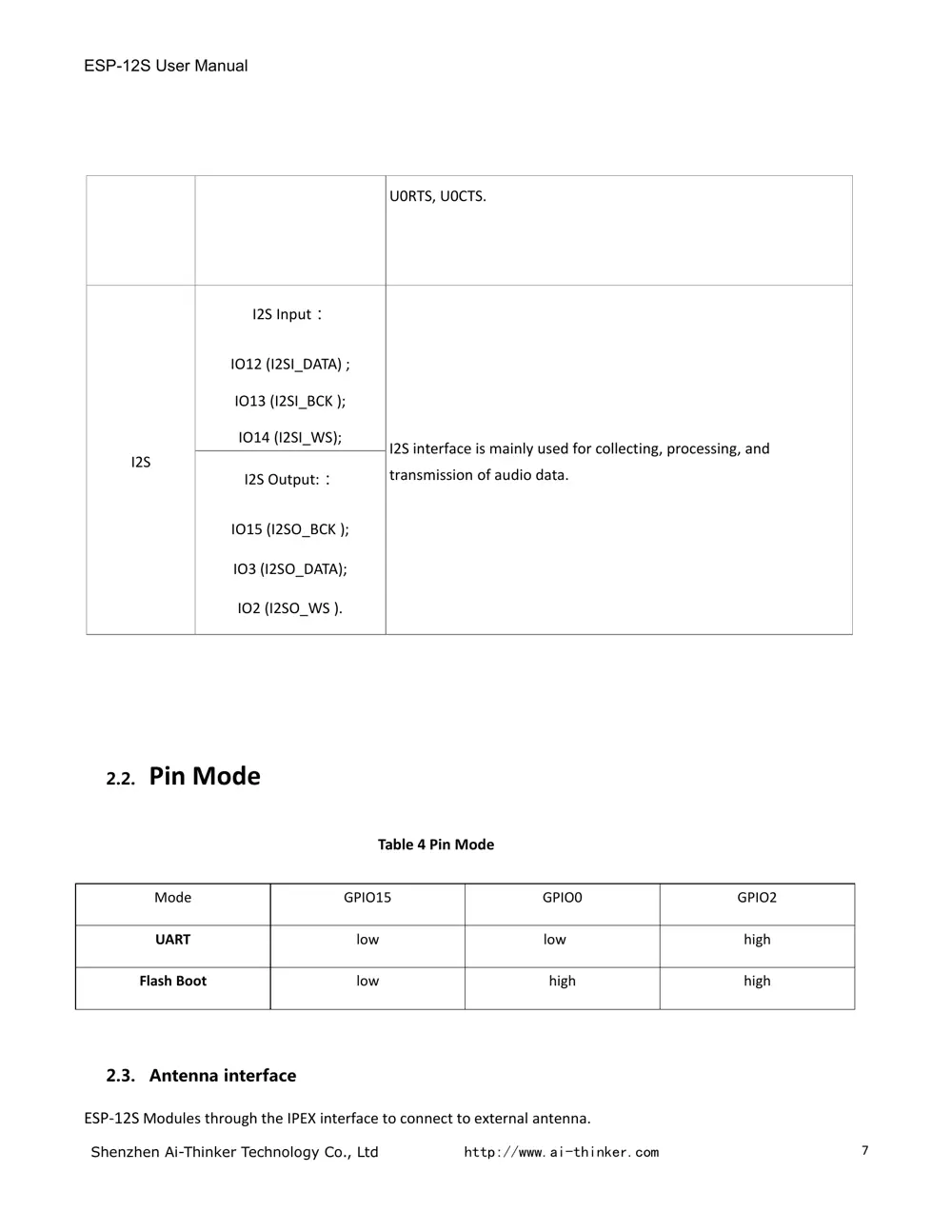
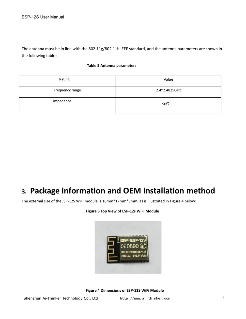
User Manual
Scanned pages from the official user manual:
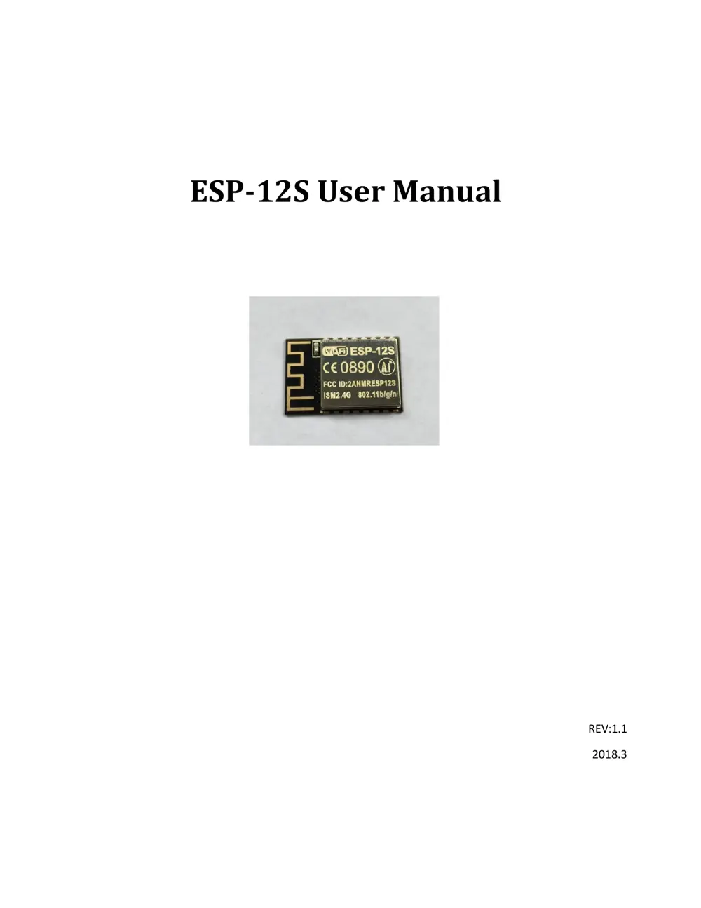
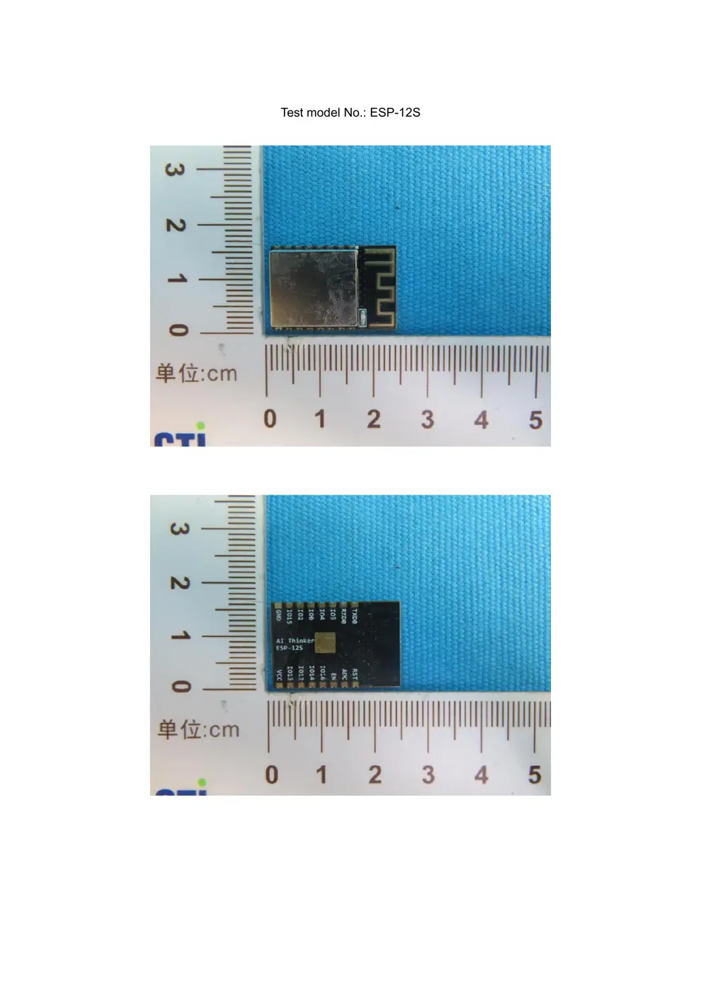
External Photos
Photos of the device exterior:
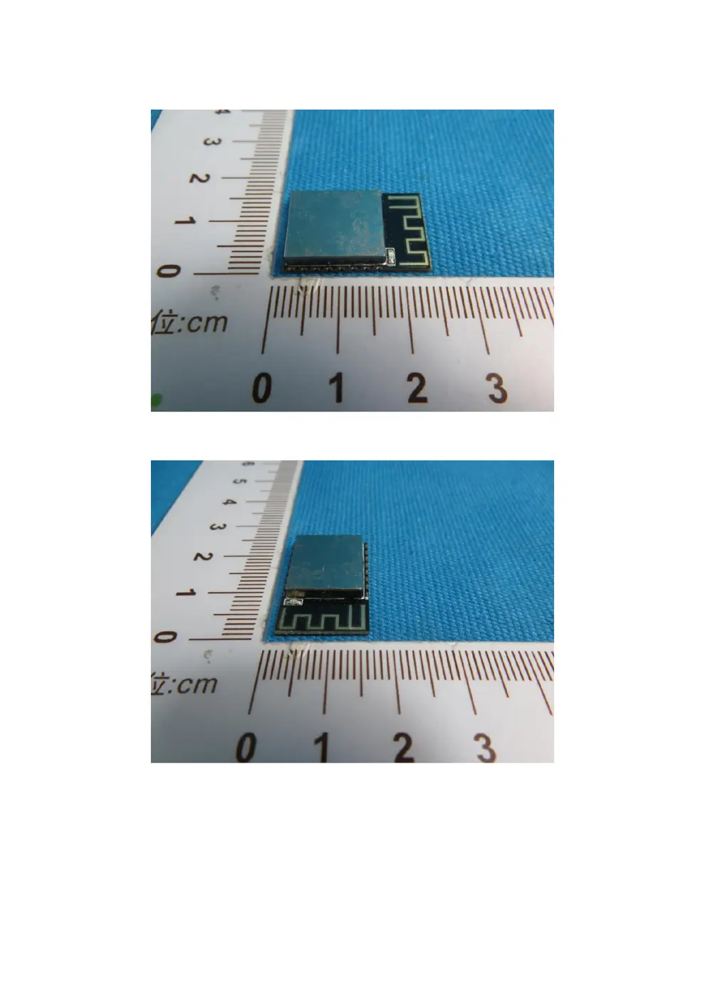
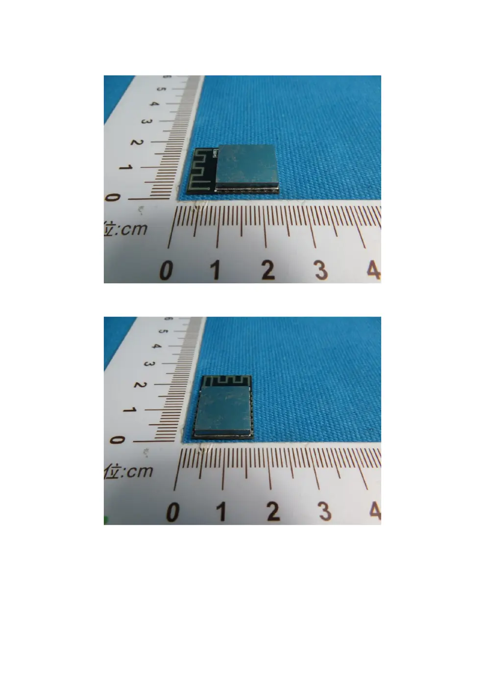
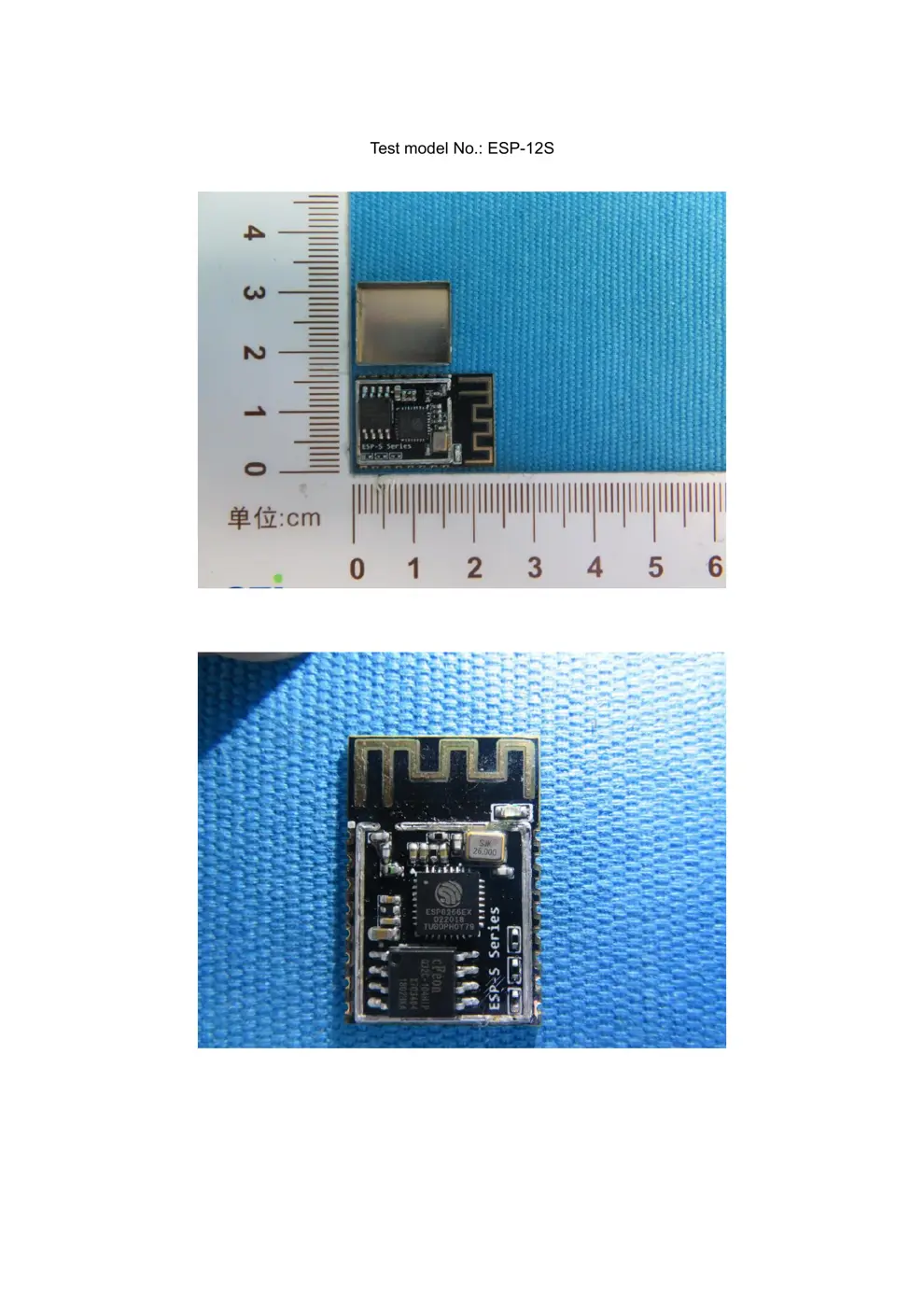
Internal Photos
Teardown photos showing the PCB and components:
Verdict
The ESP12S is a WiFi device from the Tuya / Smart Life ecosystem.
📄 Click to view full text manual (SEO)
ESP-
12
S
User
Manual
REV:1.1
2018.3
ESP-
12
S
User
Manual
Shenzhen
Ai-Thinker
Technology
Co
.,
L
td
http://www.ai-thinker.com
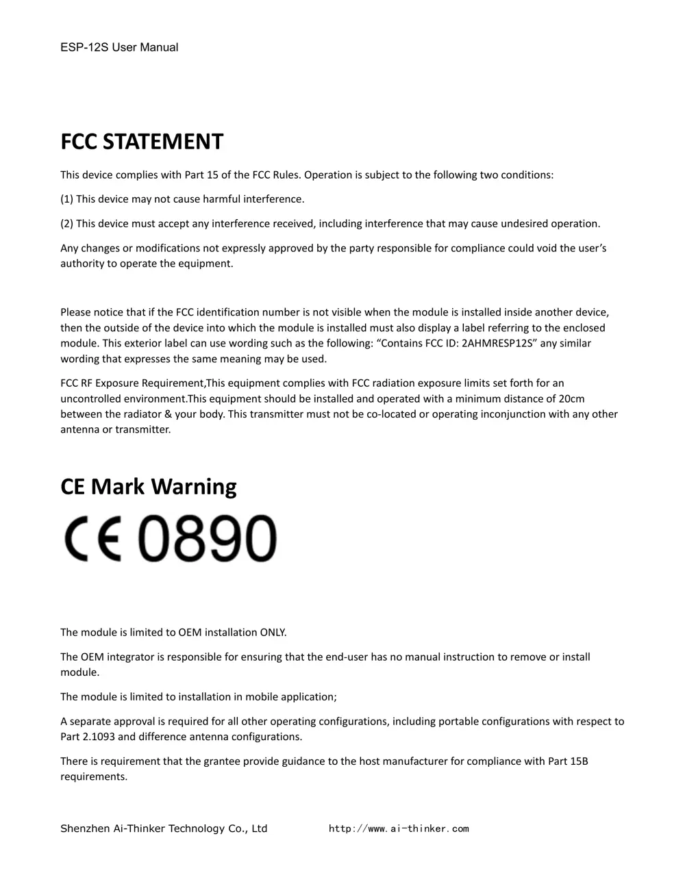
FCC
STATEMENT
This
device
complies
with
Part
15
of
the
FCC
Rules.
Operation
is
subject
to
the
following
two
conditions:
(1)
T
his
device
may
not
cause
harmful
interference
.
(2)
T
his
device
must
accept
any
interference
received,
including
interference
that
may
cause
undesired
operation.
Any
changes
or
modifications
not
expressly
approved
by
the
party
responsible
for
compliance
could
void
the
user
s
authority
to
operate
the
equipment.
Please
notice
that
if
the
FCC
identification
number
is
not
visible
when
the
module
is
installed
inside
another
device,
then
the
outside
of
the
device
into
which
the
module
is
installed
must
also
display
a
label
referring
to
the
enclosed
module.
This
exterior
label
can
use
wording
such
as
the
following:
Contains
FCC
ID:
2AHMRESP
12
S
any
similar
wording
that
expresses
the
same
meaning
may
be
used.
FCC
RF
Exposure
Requirement
,
This
equipment
complies
with
FCC
radiation
exposure
limits
set
forth
for
an
uncontrolled
environment.This
equipment
should
be
installed
and
operated
with
a
minimum
distance
of
20cm
between
the
radiator
&
your
body.
This
transmitter
must
not
be
co-located
or
operating
inconjunction
with
any
other
antenna
or
transmitter.
CE
Mark
Warning
The
module
is
limited
to
OEM
installation
ONLY .
The
OEM
integrator
is
responsible
for
ensuring
that
the
end-user
has
no
manual
instruction
to
remove
or
install
module.
The
module
is
limited
to
installation
in
mobile
application;
A
separate
approval
is
required
for
all
other
operating
configurations,
including
portable
configurations
with
respect
to
Part
2.1093
and
difference
antenna
configurations.
There
is
requirement
that
the
grantee
provide
guidance
to
the
host
manufacturer
for
compliance
with
Part
15B
requirements.
ESP-
12
S
User
Manual
Shenzhen
Ai-Thinker
Technology
Co
.,
L
td
http://www.ai-thinker.com
1
Table
Of
Contents
1.
Preambles
...............................................................................................................................................................
2
1.1.
Features
................................................................................................................................................
2
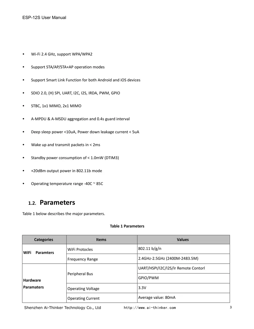
1.2.
Parameters
...........................................................................................................................................
3
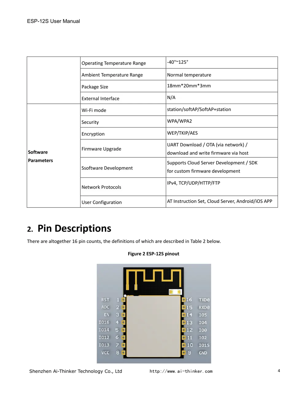
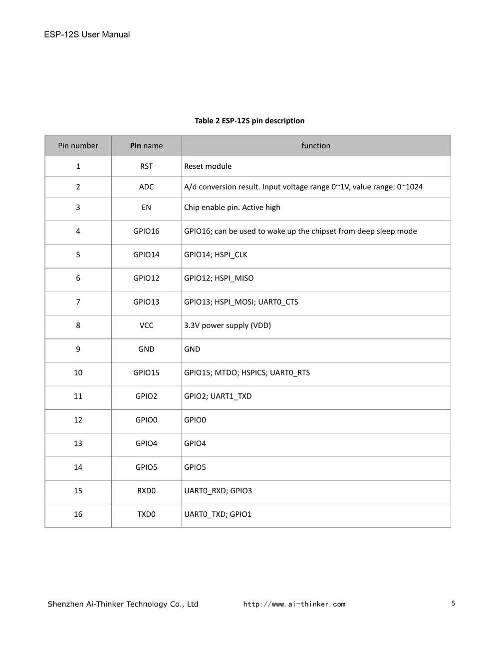
2.
Pin
Descriptions
......................................................................................................................................................
4
2.1.
Interfaces
..............................................................................................................................................
6
2.2.
Pin
Mode
..............................................................................................................................................
7
2.3.
Antenna
interface
........................