WR3L Reset & Teardown (FCC ID 2ANDL-WR3L)
Factory reset and internal photos for Tuya Global WR3L. Tuya / Smart Life smart plug.
Before you buy the Tuya Global WR3L, check what's inside.
The WR3L is a compact, low-power Wi-Fi module based on the RTL8710BX chipset, designed for integration into various smart home and IoT devices. It operates on a low voltage supply and is intended for embedded applications rather than standalone consumer products.
⚠️ NOTE: Ensure correct battery polarity and voltage when powering the module. Avoid exceeding the 3.6V maximum supply voltage.
Quick Specs
- Manufacturer: Tuya Global
- Model: WR3L
- Protocol: WiFi
- Chipset: Realtek RTL8720
- Ecosystem: Tuya / Smart Life
- App: Smart Life
🔧 Geek Corner (Flashing Info)
- Chipset: RTL8710BX
- Flashable: ❌ No
- Info: Based on common knowledge of RTL8710BX modules in the Tuya ecosystem, they are typically locked down by the manufacturer and not designed for user flashing.
User Manual
Scanned pages from the official user manual:

External Photos
Photos of the device exterior:
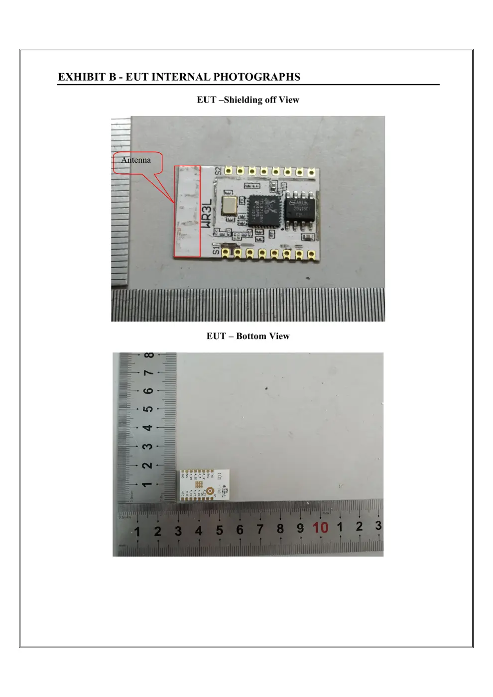
Internal Photos
Teardown photos showing the PCB and components:
Verdict
The WR3L is a WiFi device from the Tuya / Smart Life ecosystem.
📄 Click to view full text manual (SEO)
WR3LV1.0.0 User Manual
Version1.0.0
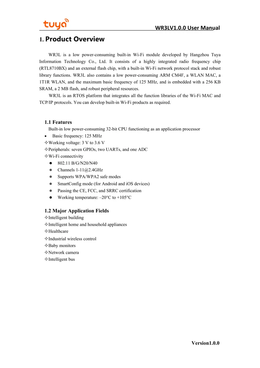
1. Product Overview
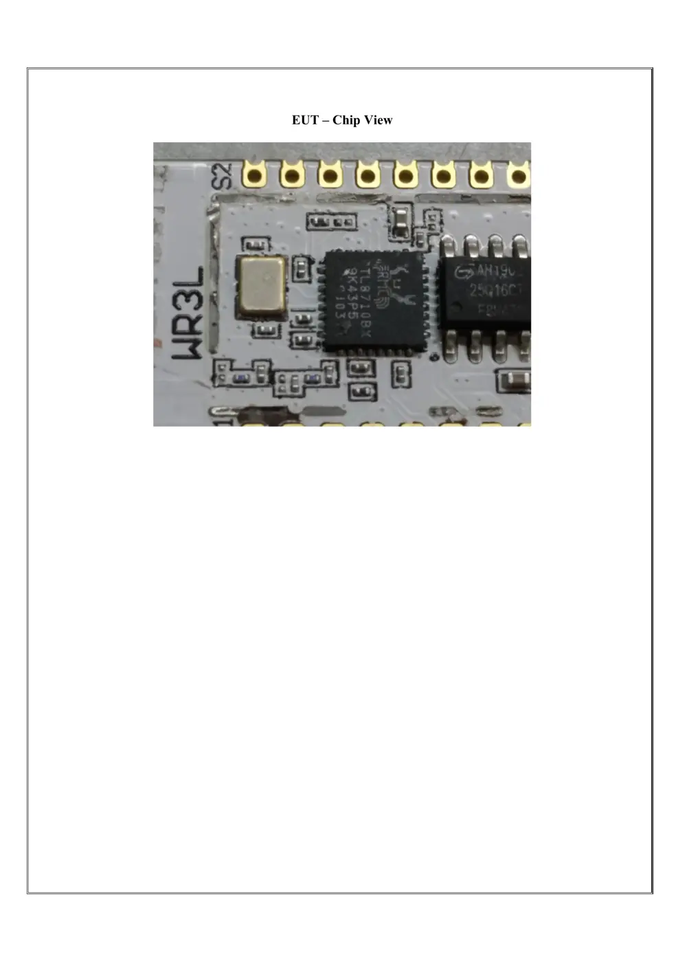
WR3L is a low power-consuming built-in Wi-Fi module developed by Hangzhou Tuya
Information Technology Co., Ltd. It consists of a highly integrated radio frequency chip
(RTL8710BX) and an external flash chip, with a built-in Wi-Fi network protocol stack and robust
library functions. WR3L also contains a low power-consuming ARM CM4F, a WLAN MAC, a
1T1R WLAN, and the maximum basic frequency of 125 MHz, and is embedded with a 256 KB
SRAM, a 2 MB flash, and robust peripheral resources.
WR3L is an RTOS platform that integrates all the function libraries of the Wi-Fi MAC and
TCP/IP protocols. You can develop built-in Wi-Fi products as required.
1.1 Features
Built-in low power-consuming 32-bit CPU functioning as an application processor
Basic frequency: 125 MHz
Working voltage: 3 V to 3.6 V
Peripherals: seven GPIOs, two UARTs, and one ADC
Wi-Fi connectivity
802.11 B/G/N20/N40
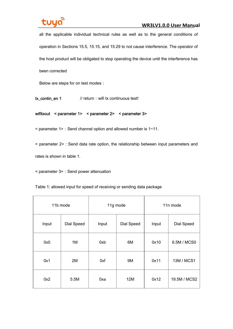
Channels [email protected]
Supports WPA/WPA2 safe modes
SmartConfig mode (for Android and iOS devices)
Passing the CE, FCC, and SRRC certification
Working temperature: –20°C to +105°C
1.2 Major Application Fields
Intelligent building
Intelligent home and household appliances
Healthcare
Industrial wireless control
Baby monitors
Network camera
Intelligent bus
WR3LV1.0.0 User Manual
Version1.0.0
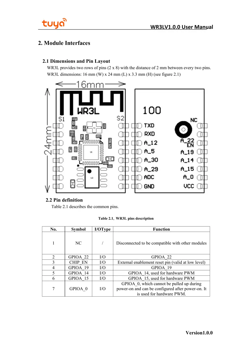
2. Module Interfaces
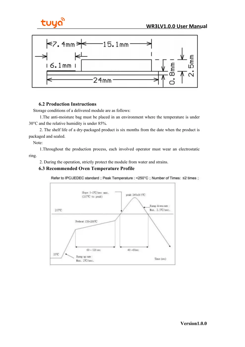
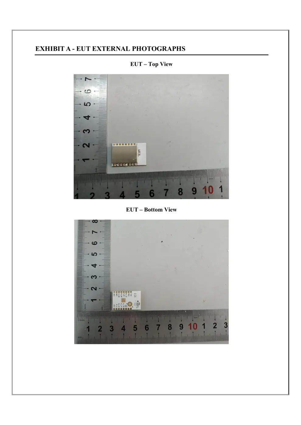
2.1 Dimensions and Pin Layout
WR3L provides two rows of pins (2 x 8) with the distance of 2 mm between every two pins.
WR3L dimensions: 16 mm (W) x 24 mm (L) x 3.3 mm (H) (see figure 2.1)
2.2 Pin definition
Table 2.1 describes the common pins.
Table 2.1,WR3L pins description
No. Symbol I/OType Function
1 NC / Disconnected to be compatible with other modules
2 GPIOA_22 I/O GPIOA_22
3 CHIP_EN I/O External enablement reset pin (valid at low level)
4 GPIOA_19 I/O GPIOA_19
5 GPIOA_14 I/O GPIOA_14, used for hardware PWM
6 GPIOA_15 I/O GPIOA_15, used for hardware PWM
7 GPIOA_0 I/O
GPIOA_0, which cannot be pulled up during
power-on and can be configured after power-on. It
is used for hardware PWM.
WR3LV1.0.0 User Manual
Version1.0.0
8 VD33 P Module power supply pin (3.3 V)
9 GND P Power supply reference ground pin
10 ADC AI ADC port, with the maximum input voltage of 5 V
11 GPIOA_29 I/O UART_Log_RXD (used for printing the internal
information of
the module)
12 GPIOA_30 I/O UART_Log_TXD (used for printing the internal
information of the module)
13 GPIOA_5 I/O GPIOA_5, used for hardware PWM
14 GPIOA_12 I/O GPIOA_12, used for hardware PWM
15 RXD I/O UART0_RXD (user’s serial port)
16 TXD I/O UART0_TXD (user’s serial port)
Note: P indicates power-supply pins, I/O indicates input/output pins, and AI indicates
analog input pins.
3. Electrical Parameters
3.1 Absolute electrical parameters
Table 3.1,Absolute Parameters
Parameters Description Minimu
m value
Maximu
m value Unit
Ts Storage
temperature –40 125 °C
VDD Power-supply
voltage –0.3 3.6 V
Static electricity voltage
(h...