1312PSIP Reset & Teardown (FCC ID 2AB2Q-1312PSIP)
Factory reset and internal photos for Broadlink 1312PSIP. Broadlink smart plug.
January 16, 2026
•
8 read

Before you buy the Broadlink 1312PSIP, check what's inside.
This Broadlink device, identified by FCC ID 2AB2Q-1312PSIP, is a WiFi-enabled smart home controller. It likely functions as an IR or RF remote to control other appliances, integrating with the Broadlink App ecosystem.
⚠️ NOTE: Ensure the device is connected to a properly rated mains power outlet and that installation adheres to local electrical codes.
Quick Specs
- Manufacturer: Broadlink
- Model: 1312PSIP
- Protocol: WiFi
- Chipset: Broadlink WiFi
- Ecosystem: Broadlink
- App: Broadlink App
🔧 Geek Corner (Flashing Info)
- Chipset: Broadlink WiFi
- Flashable: ❌ No
- Info: Proprietary Broadlink chipset and firmware, not designed for flashing custom firmware like Tasmota or ESPHome.
User Manual
Scanned pages from the official user manual:
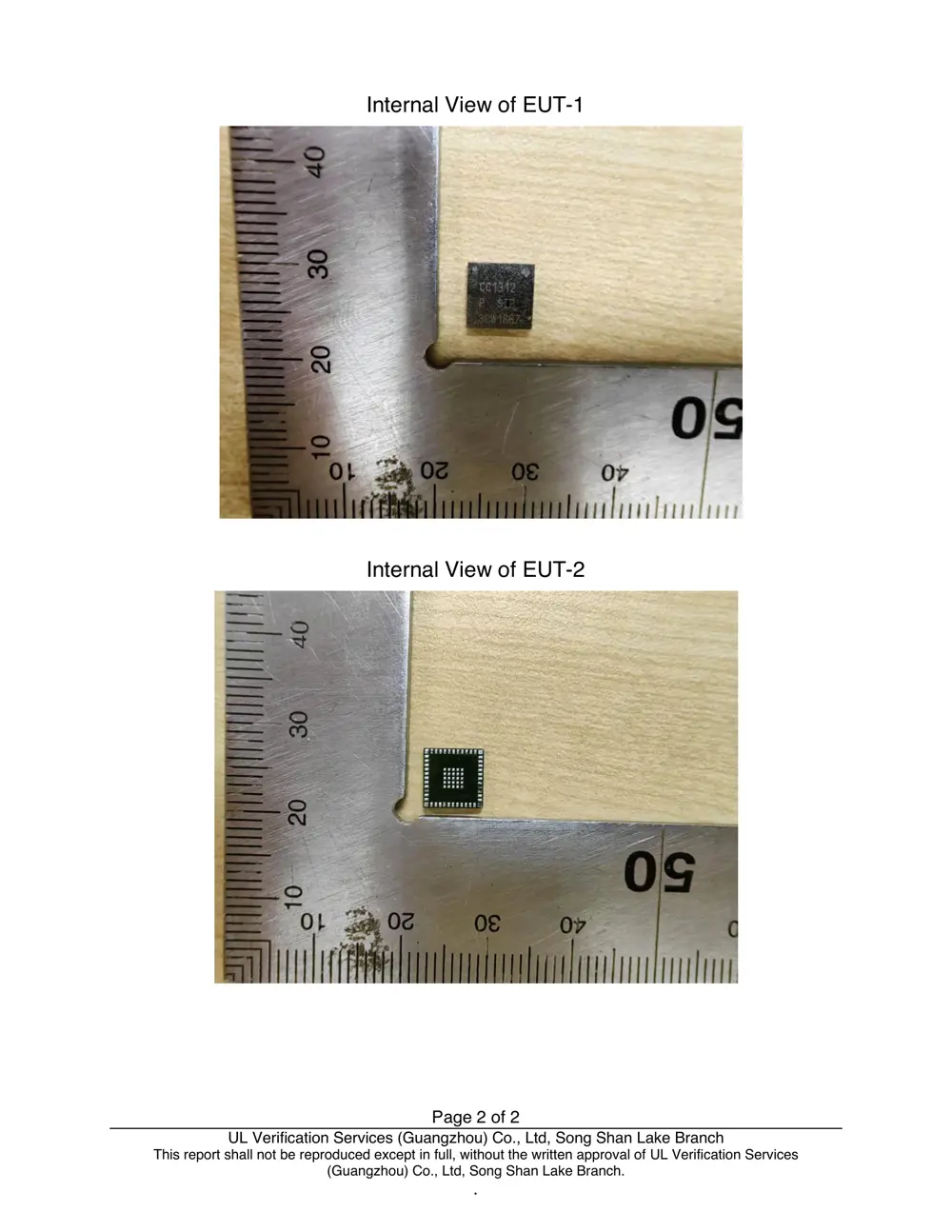
Internal Photos
Teardown photos showing the PCB and components:
Verdict
The 1312PSIP is a WiFi device from the Broadlink ecosystem.
📄 Click to view full text manual (SEO)
PAGE 1 OF 8 Version 1.0
FCC Statement
This equipment has been tested and found to comply with the limits for a Class B digital device, pursuant to part
15 of the FCC rules. These limits are designed to provide reasonable protection against harmful interference in a
residential installation. This equipment generates, uses and can radiate radio frequency energy and, if not installed
and used in accordance with the instructions, may cause harmful interference to radio communications. However,
there is no guarantee that interference will not occur in a particular installation. If this equipment does cause
harmful interference to radio or television reception, which can be determined by turning the equipment off and
on, the user is encouraged to try to correct the interference by one or more of the following measures:
-Reorient or relocate the receiving antenna.
-Increase the separation between the equipment and receiver.
-Connect the equipment into an outlet on a circuit different from that to which the receiver is connected.
-Consult the dealer or an experienced radio/TV technician for help.
This equipment complies with Part 15 of the FCC Rules. Operation is subject to the following two conditions:
(1) This device may not cause harmful interference, and
(2) This device must accept any interference received, including interference that may cause undesired operation.
Any changes or modifications not expressly approved by the party responsible for compliance could void the
user’s authority to operate the equipment.
2.2
This module has been assessed against the following FCC rule parts: CFR 47 FCC Part 15 C DSS) .It
is applicable to the modular transmitter
2.3
This radio transmitter 2AB2Q-1312PSIP has been approved by Federal Communications Commission to operate
with the antenna types listed below, with the maximum permissible gain indicated. Antenna types not included in
this list that have a gain greater than the maximum gain indicated for any type listed are strictly prohibited for use
with this device.
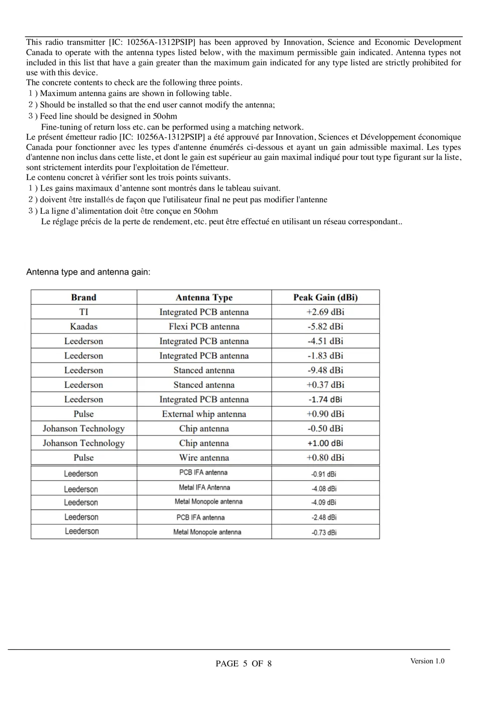
The concrete contents to check are the following three points.
1) Maximum antenna gains are shown in item 2.7 below.
2) Should be installed so that the end user cannot modify the antenna
3) Feed line should be designed in 50ohm
Fine-tuning of return loss etc. can be performed using a matching network.
The antenna shall not be accessible for modification or change by the end user.
2.4
The module complies with FCC Part 15.247 and apply for Single module approval.
2.5
Trace antenna designs: applicable. The trace reference design information in the operational description is confidential.
grantee will share the trace design to the OEM when sale out these modules.
Any deviation(s) from the defined parameters of the antenna trace, as described by the instructions, require that the
host product manufacturer must notify the module grantee that they wish to change the antenna trace design. In this
case, a Class II p...