TYZS1 Reset & Teardown (FCC ID 2ANDL-TYZS1)
Factory reset and internal photos for Tuya Global TYZS1. Tuya / Smart Life smart plug.
January 15, 2026
•
8 read
Before you buy the Tuya Global TYZS1, check what's inside.
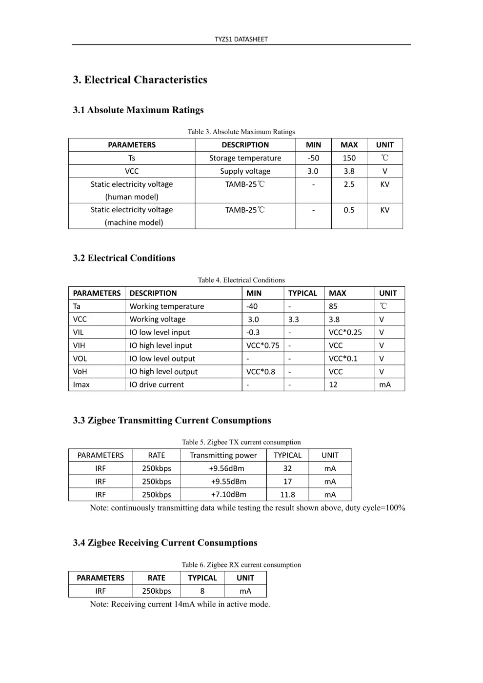
The Tuya TYZS1 is a low-power Zigbee module featuring an EFR32MG1B132 chipset, designed for integration into smart home devices. It operates on a DC3.3V supply and is suitable for various intelligent building and household applications.
⚠️ NOTE: Ensure correct battery polarity when installing.
Quick Specs
- Manufacturer: Tuya Global
- Model: TYZS1
- Protocol: Zigbee
- Chipset: Tuya Zigbee
- Ecosystem: Tuya / Smart Life
- App: Smart Life
🔧 Geek Corner (Flashing Info)
- Chipset: EFR32MG1B132
- Flashable: ❌ No
- Info: Based on the EFR32MG1B132 chipset, it is unlikely to be flashable with common firmware like Tasmota without significant custom development.
User Manual
Scanned pages from the official user manual:


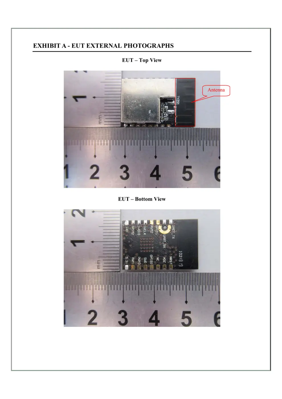
External Photos
Photos of the device exterior:
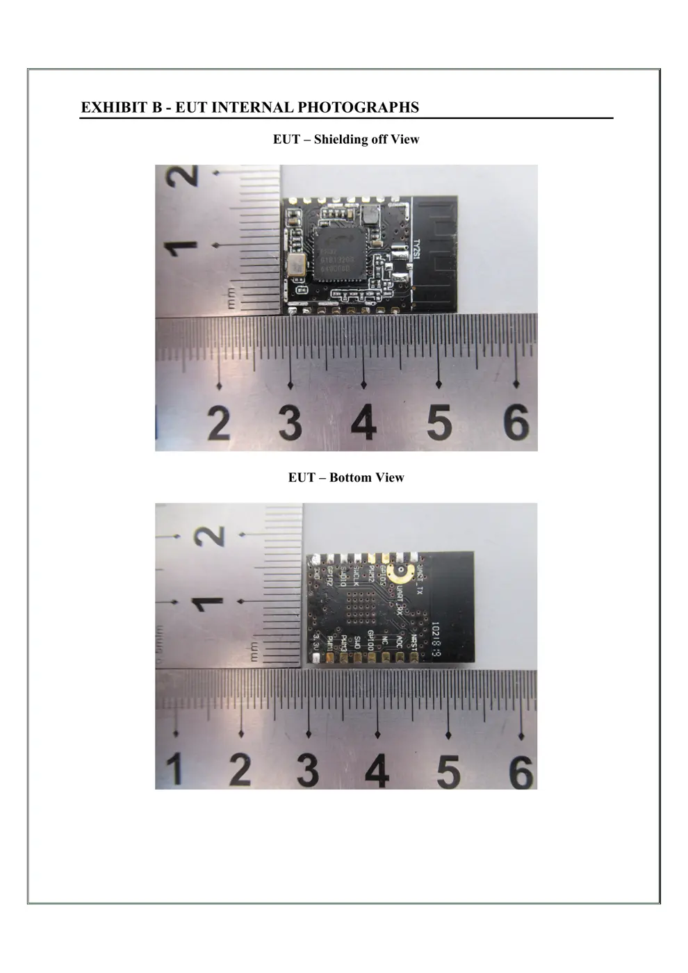
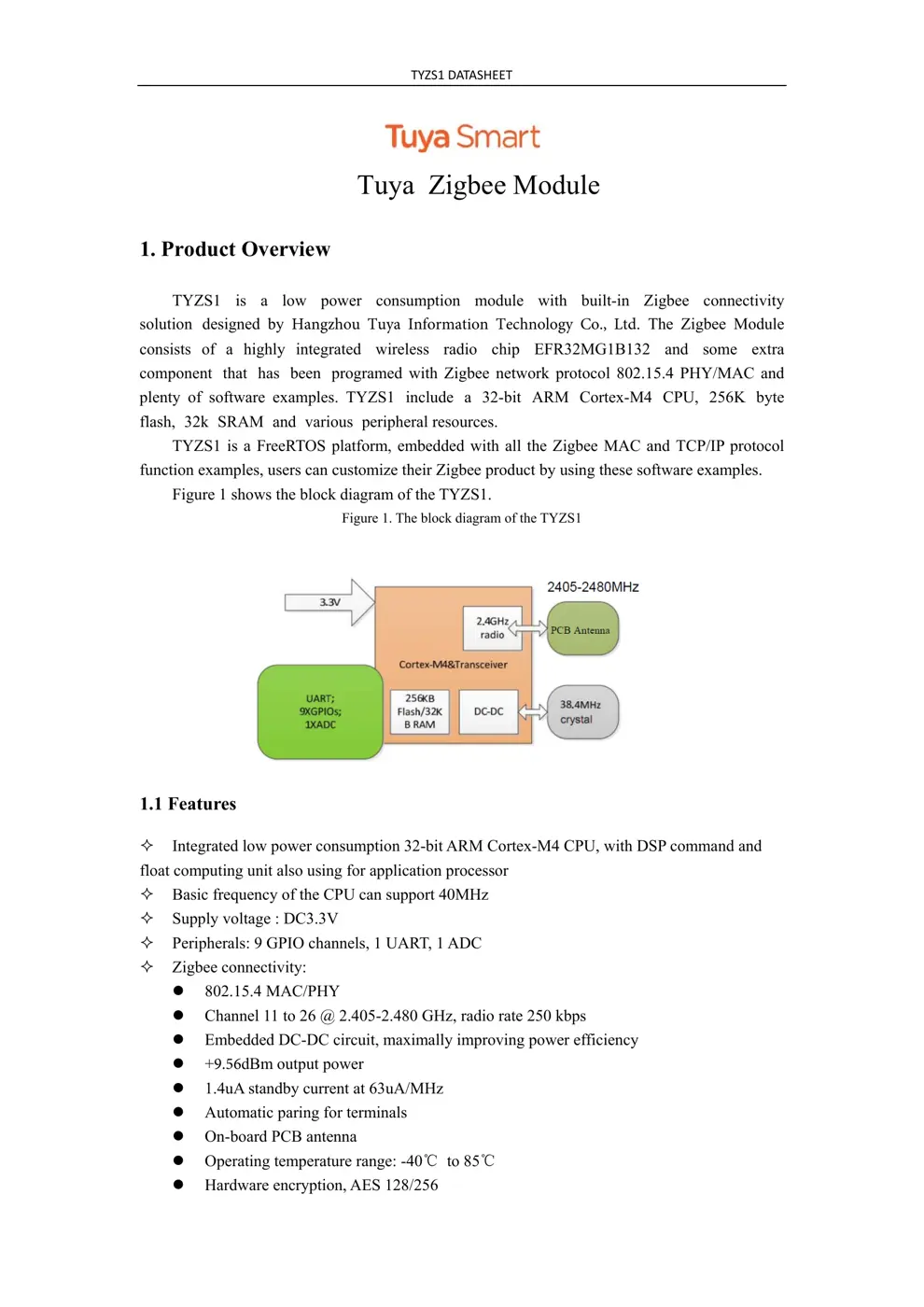
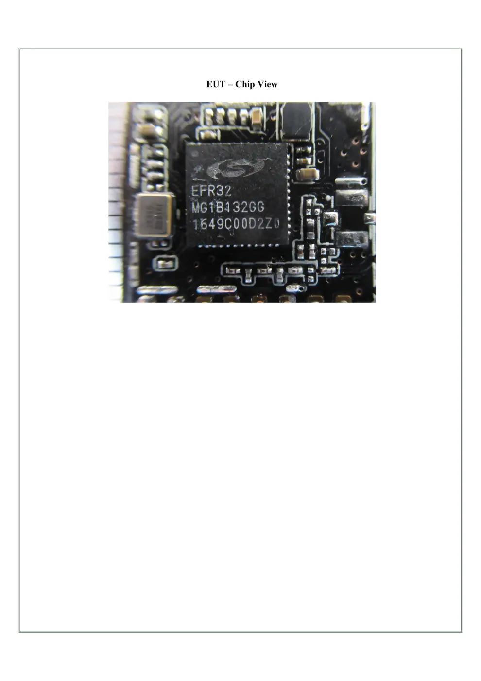
Internal Photos
Teardown photos showing the PCB and components:

Verdict
The TYZS1 is a Zigbee device from the Tuya / Smart Life ecosystem.
📄 Click to view full text manual (SEO)
TY
ZS1DATASHEET
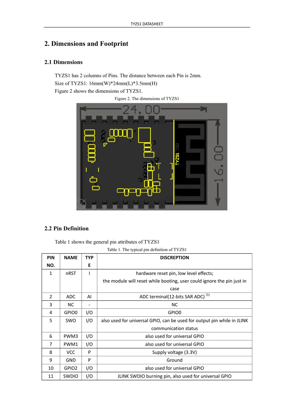
Tuya Zigbee Module
1. Product Overview
TYZS1 is a low power co nsumption module with built-in Zigbee connectivity
solution designed by Hangzhou Tuya Information Technology Co., Ltd. The Zigbee Module
consists of a highly integrated wireless radio chip EFR32MG1B132 and some extra
component that has been programed with Zigbee network protocol 802.15.4 PHY/MAC and
plenty of software examples. TYZS1 include a 32-bit ARM Cortex-M4 CPU, 256K byte
flash, 32k SRAM and various peripheral resources.
TYZS1 is a FreeRTOS platform, embedded with all the Zigbee MAC and TCP/IP protocol
function examples, users can customize their Zigbee product by using these software examples.
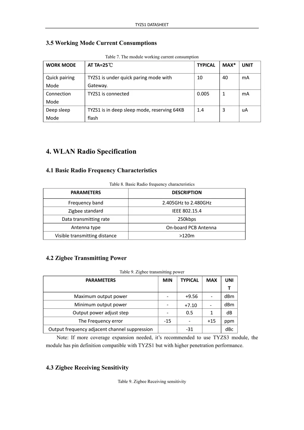
Figure 1 shows the block diagram of the TYZS1.
Figure 1. The block diagram of the TYZS1
1.1 Features
Integrated low power consumption 32-bit ARM Cortex-M4 CPU, with DSP command and
float computing unit also using for application processor
Basic frequency of the CPU can support 40MHz
Supply voltage : DC3.3V
Peripherals: 9 GPIO channels, 1 UART, 1 ADC
Zigbee connectivity:
802.15.4 MAC/PHY
Channel 11 to 26 @ 2.405-2.480 GHz, radio rate 250 kbps
Embedded DC-DC circuit, maximally improving power efficiency
+9.56dBm output power
1.4uA standby current at 63uA/MHz
Automatic paring for terminals
On-board PCB antenna
Operating temperature range: -40℃ to 85 ℃
Hardware encryption, AES 128/256
TYZS1DATASHEET
1.2 Main Application Fields
Intelligent Building
Intelligent home, Intelligent household applications
Smart socket, smart lighting
Industrial wireless control
Health and measurement management
Asset trace
TYZS1DATASHEET
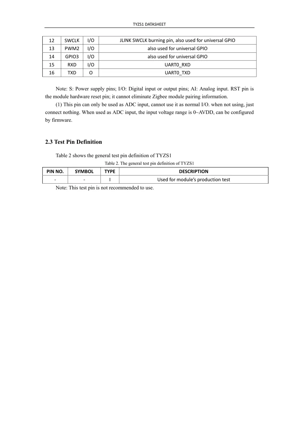
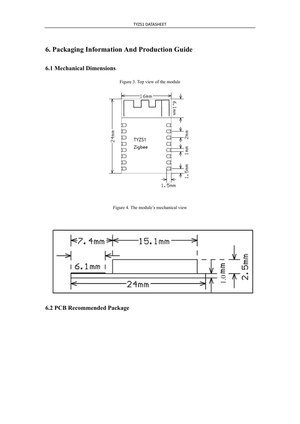
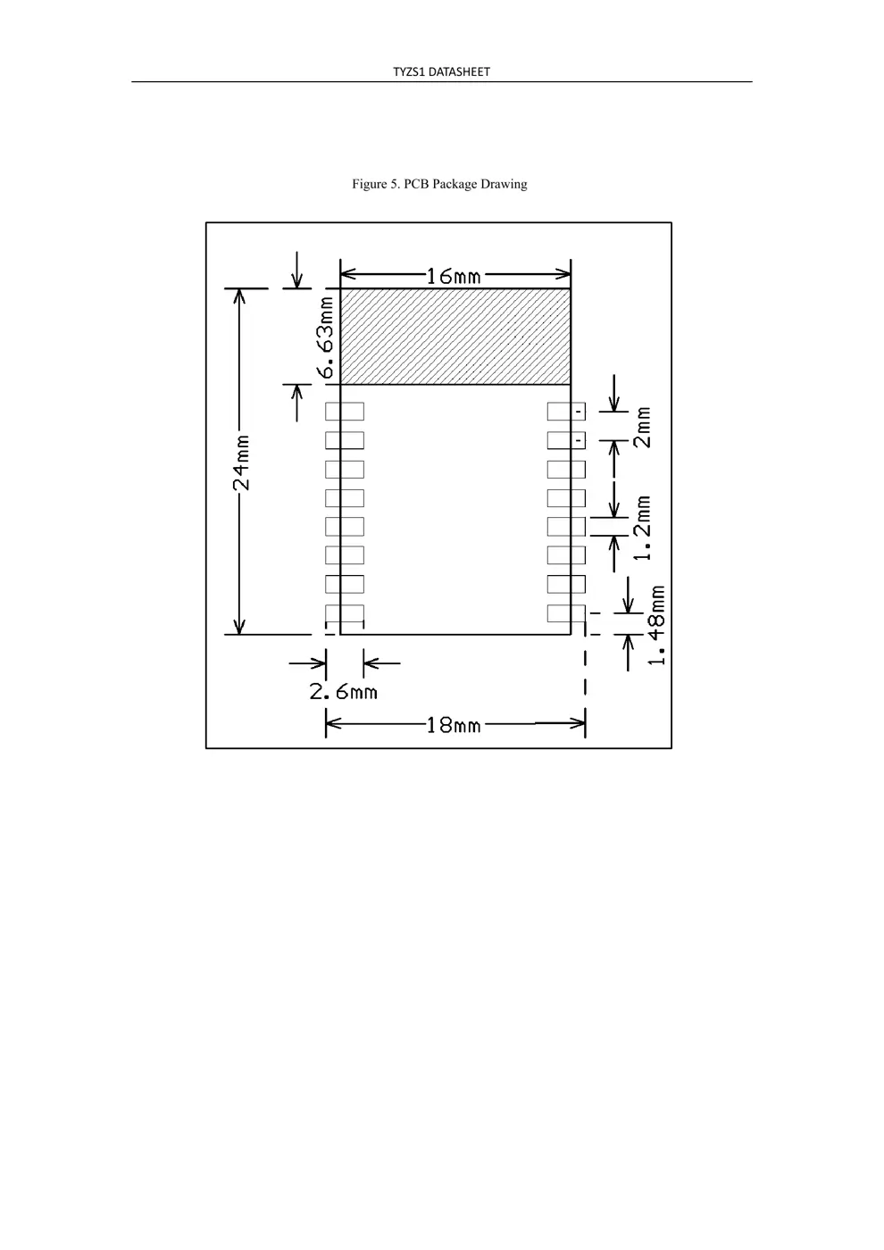
2. Dimensions and Footprint
2.1 Dimensions
TYZS1 has 2 columns of Pins. The distance between each Pin is 2mm.
Size of TYZS1: 16mm(W)*24mm(L)*3.5mm(H)
Figure 2 shows the dimensions of TYZS1.
Figure 2. The dimensions of TYZS1
2.2 Pin Definition
Table 1 shows the general pin attributes of TYZS1
Table 1. The typical pin definition of TYZS1
PIN
NO.
NAME TYP
E
DISCREPTION
1 nRST I hardwareresetpin,lowleveleffects;
themodulewillresetwhilebooting,usercouldignorethepinjustin
case
2 ADC AI ADCterminal(12‐bitsSARADC)
(1)
3 NC‐ NC
4 GPIO0 I/O GPIO0
5 SWO I/O alsousedforuniversalGPIO,canbeusedforoutputpinwhileinJLINK
communicationstatus
6 PWM3 I/O alsousedforuniversalGPIO
7 PWM1 I/O alsousedforuniversalGPIO
8 VCC P Supplyvoltage(3.3V)
9 GND P Ground
10 GPIO2 I/O alsousedforuniversalGPIO
11 SWDIO I/O JLINKSWDIOburningpin,alsousedforuniversalGPIO
TYZS1DATASHEET
12 SWCLK I/O JLINKSWCLKburningpin,alsousedforuniversalGPIO
13 PWM2 I/O alsousedforuniversalGPIO
14 GPIO3 I/O alsousedforuniversalGPIO
15 RXD I/O UART0_RXD
16 TXD O UART0_TXD
Note: S: P ower supply pins; I/O: Digital input or output pins; AI: Analog input. RST pin is
the module hardware reset pin; it cannot eliminate Zigbee module pairing information.
(1) This pin can only be used as ADC input, cannot use it as normal I/O. when not using, just
connect nothing. When used as ADC ...