WT1HB12 Reset & Teardown (FCC ID 2ACDZ-WT1HB12)
Factory reset and internal photos for Broadlink WT1HB12. Broadlink smart plug.
January 15, 2026
•
8 read

Before you buy the Broadlink WT1HB12, check what's inside.
The Broadlink WT1HB12 is an embedded 2.4GHz Wi-Fi module designed for IoT applications. It offers Wi-Fi connectivity, suitable for home automation and lighting control systems, and communicates via UART.
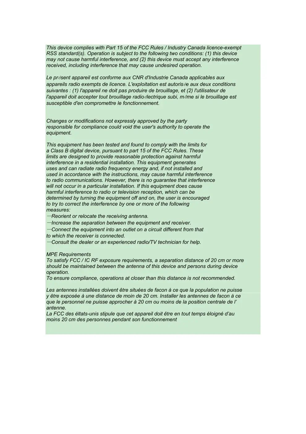
⚠️ NOTE: Ensure the 12V DC power supply is correctly connected and polarity is observed. Avoid exceeding the maximum supply voltage of 16V.
Quick Specs
- Manufacturer: Broadlink
- Model: WT1HB12
- Protocol: WiFi
- Chipset: Broadlink WiFi
- Ecosystem: Broadlink
- App: Broadlink App
🔧 Geek Corner (Flashing Info)
- Chipset: Broadlink WiFi (Specific Chipset Unknown)
- Flashable: ❌ No
- Info: The module is a Wi-Fi SoC from Broadlink, which typically uses proprietary firmware and is not designed for flashing custom firmware like Tasmota or ESPHome.
User Manual
Scanned pages from the official user manual:

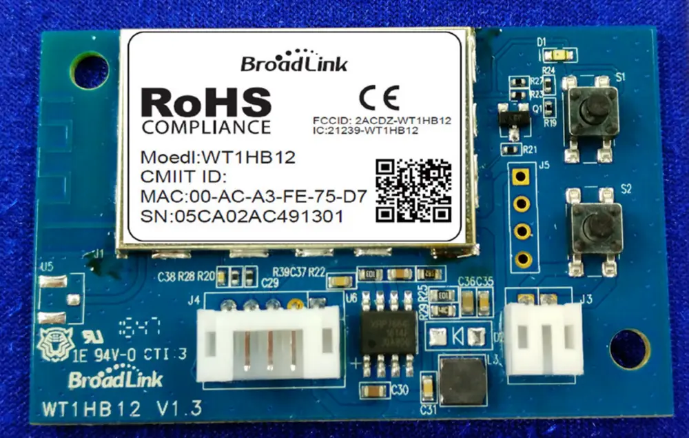
External Photos
Photos of the device exterior:
Verdict
The WT1HB12 is a WiFi device from the Broadlink ecosystem.
📄 Click to view full text manual (SEO)
Wi-Fi Module User Manual
Model: WT1HB12
V 1.5
1. Product Overview
1.1. Introduction
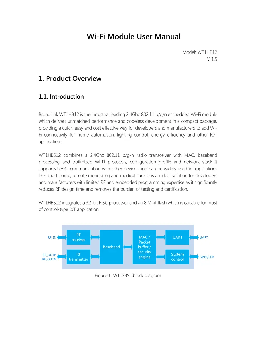
BroadLink WT1HB12 is the industrial leading 2.4Ghz 802.11 b/g/n embedded Wi-Fi module
which delivers unmatched performance and codeless development in a compact package,
providing a quick, easy and cost effective way for developers and manufacturers to add Wi-
Fi connectivity for home automation, lighting control, energy efficiency and other IOT
applications.
WT1HBS12 combines a 2.4Ghz 802.11 b/g/n radio transceiver with MAC, baseband
processing and optimized Wi-Fi protocols, configuration profile and network stack It
supports UART communication with other device s and can be widely used in applications
like smart home, remote monitoring and medical care. It is an ideal solution for developers
and manufacturers with limited RF and embedded programming expertise as it significantly
reduces RF design time and removes the burden of testing and certification.
WT1HBS12 integrates a 32-bit RISC processor and an 8 Mbit flash which is capable for most
of control-type IoT application.
RF
receiver
RF
transmitter
Baseband
MAC /
Packet
buffer /
security
engine
UART
System
control
RF_IN
RF_OUTP
RF_OUTN
UART
GPIO/LED
Figure 1. WT1SBSL block diagram
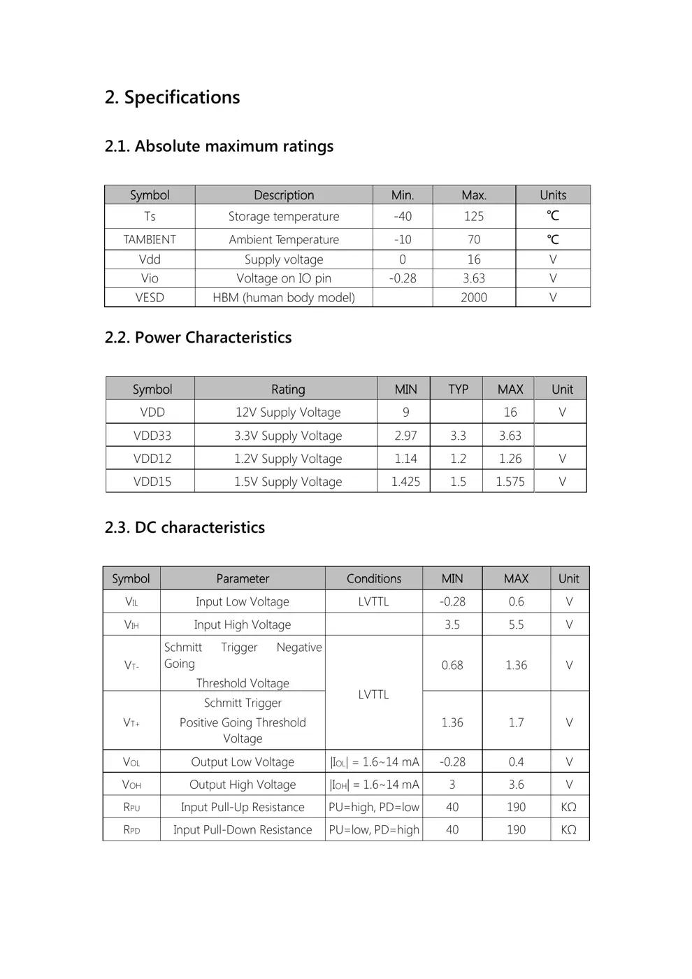
2. Specifications
2.1. Absolute maximum ratings
Symbol Description Min. Max. Units
Ts Storage temperature -40 125 ℃
TAMBIENT Ambient T emperature -10 70 ℃
Vdd Supply voltage 0 16 V
Vio Voltage on IO pin -0.28 3.63 V
VESD HBM (human body model) 2000 V
2.2. Power Characteristics
Symbol Rating MIN TYP MAX Unit
VDD 12V Supply Voltage 9 16 V
VDD33 3.3V Supply Voltage 2.97 3.3 3.63
VDD12 1.2V Supply Voltage 1.14 1.2 1.26 V
VDD15 1.5V Supply Voltage 1.425 1.5 1.575 V
2.3. DC characteristics
Symbol Parameter Conditions MIN MAX Unit
VIL Input Low Voltage LVTTL -0.28 0.6 V
VIH Input High Voltage 3.5 5.5 V
VT-
Schmitt Trigger Negative
Going
Threshold Voltage
LVTTL
0.68 1.36 V
VT+
Schmitt Trigger
Positive Going Threshold
Voltage
1.36 1.7 V
VOL Output Low Voltage |IOL| = 1.6~14 mA -0.28 0.4 V
VOH Output High Voltage |IOH| = 1.6~14 mA 3 3.6 V
RPU Input Pull-Up Resistance PU=high, PD=low 40 190 KΩ
RPD Input Pull-Down Resistance PU=low, PD=high 40 190 KΩ
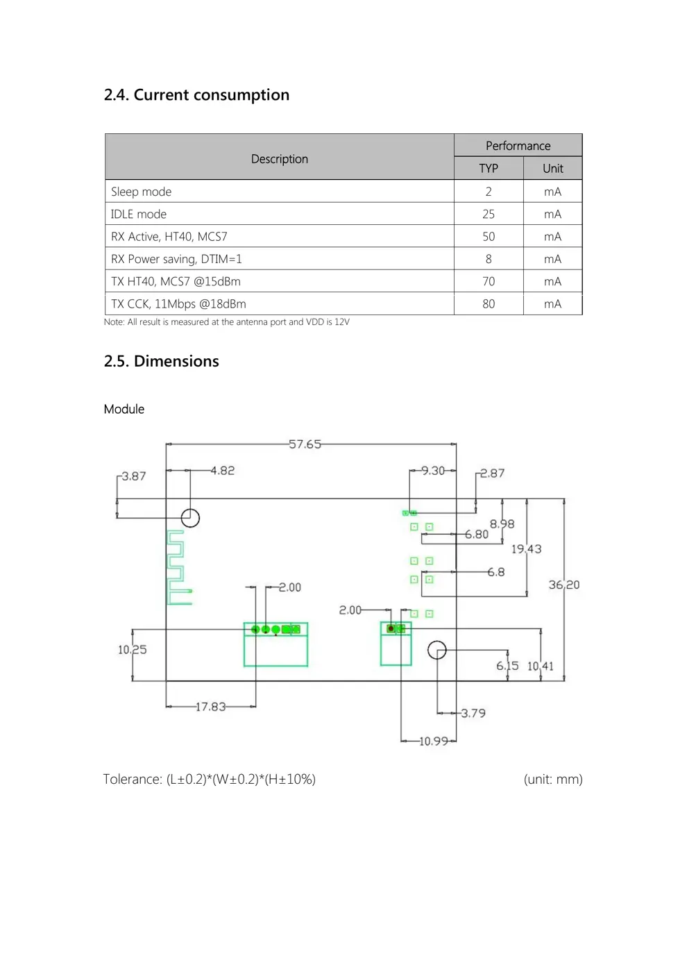
2.4. Current consumption
Description
Performance
TYP Unit
Sleep mode 2 mA
IDLE mode 25 mA
RX Active, HT40, MCS7 50 mA
RX Power saving, DTIM=1 8 mA
TX HT40, MCS7 @15dBm 70 mA
TX CCK, 11Mbps @18dBm 80 mA
Note: All result is measured at the antenna port and VDD is 12V
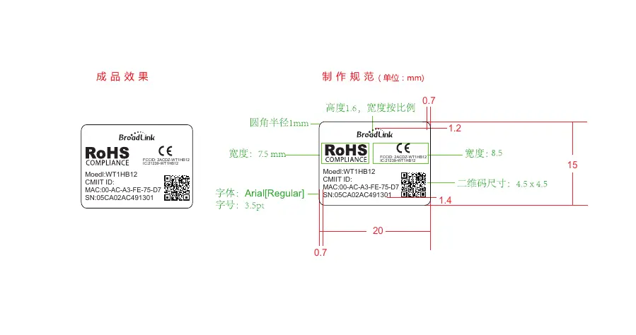
2.5. Dimensions
Module
Tolerance: (L±0.2)*(W±0.2)*(H±10%) (unit: mm)
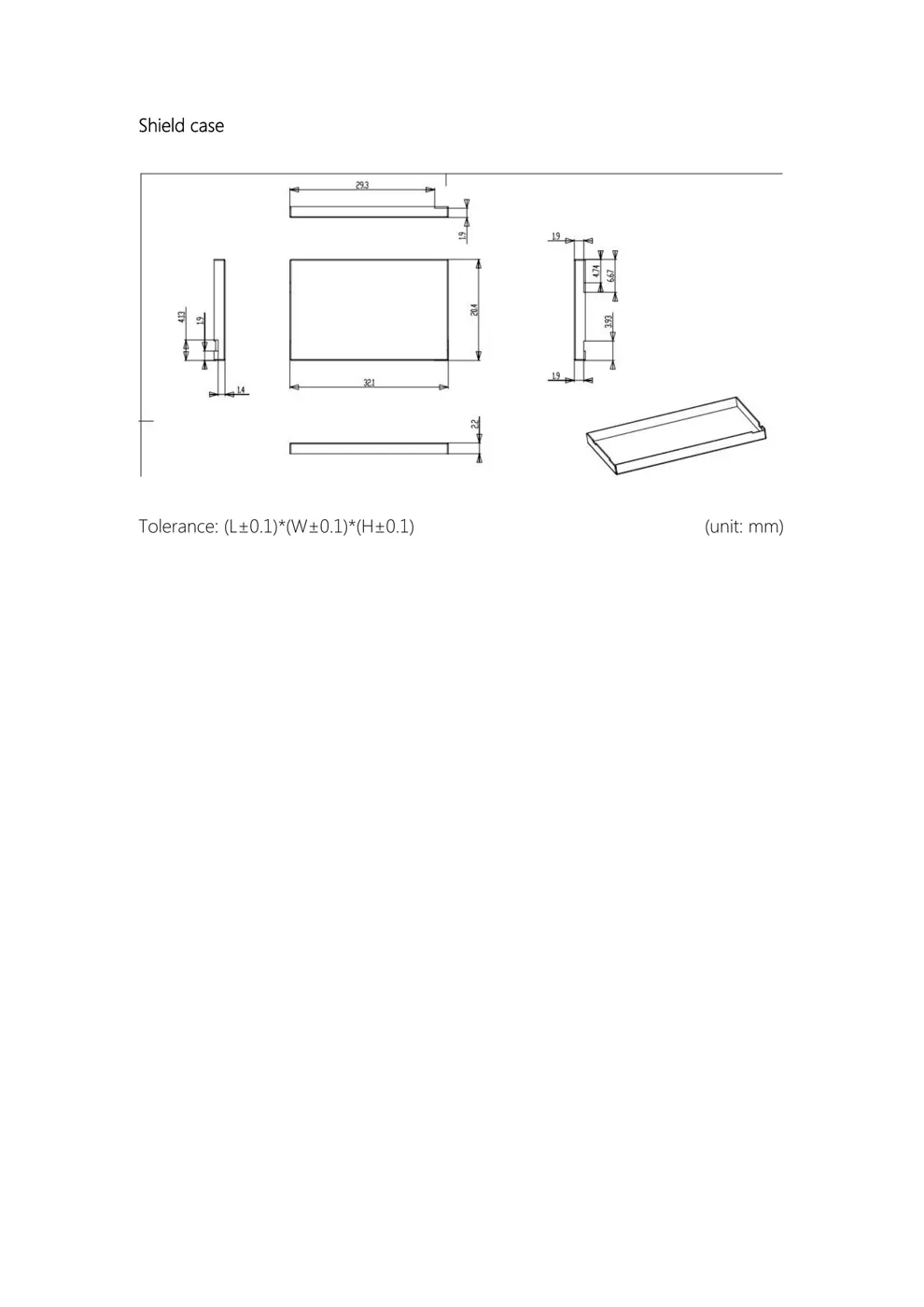
Shield case
Tolerance: (L±0.1)*(W±0.1)*(H±0.1) (unit: mm)
3. Module Interface
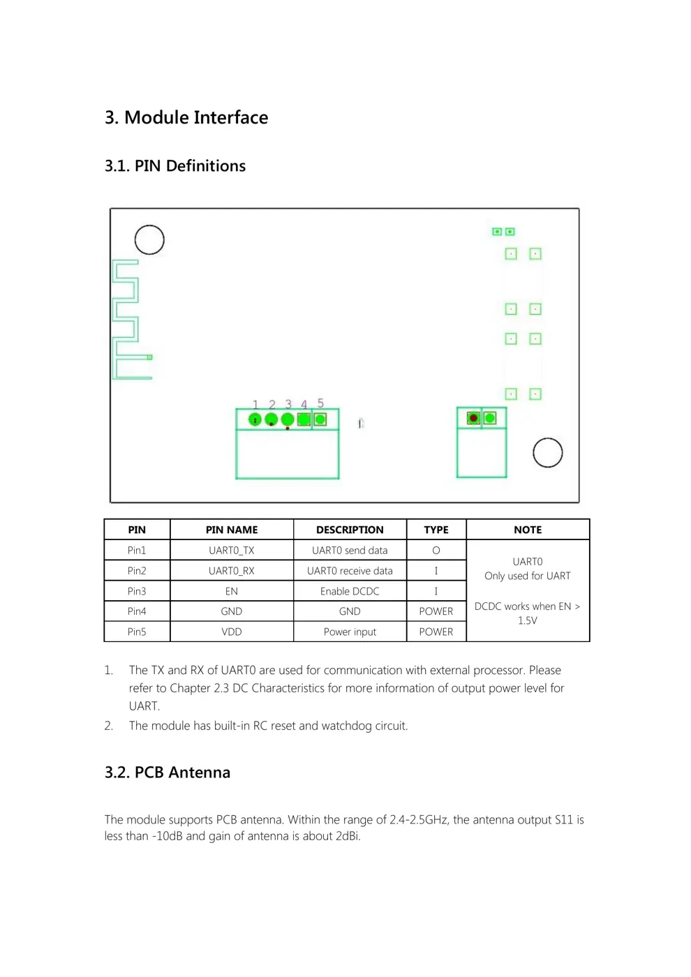
3.1. PIN Definitions
PIN PIN NAME DESCRIPTION TYPE NOTE
Pin1 UART0_TX UART0 send data O
UART0
Only used for UART
DCDC works when EN >
1.5V
Pin2 UART0_RX UART0 receive data I
Pin3 EN Enable DCDC I
Pin4 GND GND POWER
Pin5 VDD Power input POWER
1. The TX and RX of UART0 are used for communication with external p...